Beam Angle and Mounting Geometry for Narrow Tanks and Conveyor Detection
Many ultrasonic sensor projects fail even when the range looks correct on paper. The selected model can reach the target, the PLC is wired correctly, and bench testing appears clean, yet the installed system still produces unstable readings or false switching. In most of these cases the real problem is geometry.
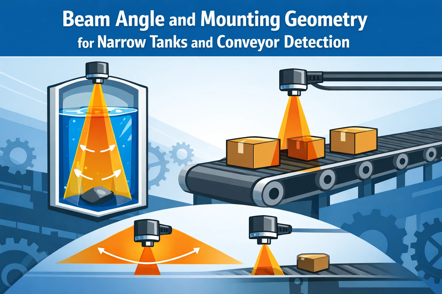
Beam angle, wall clearance, nozzle depth, bracket stiffness, and target width determine whether the acoustic path stays under control after installation. In a narrow tank, the echo can clip the side wall before it returns from the liquid surface. On a conveyor, the same geometric mistake appears when the beam catches a side rail, an adjacent lane, or a vibrating bracket instead of the intended target. Different application, same integration failure.
This article is written as a field geometry playbook for engineering teams evaluating the sensor product hub, the core MU30 sensor, and broader supplier capability through the ultrasonic transducer supplier page. It does not repeat a general M18 versus M30 comparison, and it does not re-run blind-zone theory from first principles. Its job is to show how beam angle and mounting geometry should be screened before sample approval.
Problem Context
Product path for this search intent
Match the article topic to the right Yujie product page
Use this article when sensor performance depends on target distance, beam angle, housing material, liquid behavior, or false echo control. For "Beam Angle and Mounting Geometry for Narrow Tanks and Conveyor Detection", the practical value is in turning the topic into a measurable selection or sourcing decision.
- Ultrasonic Sensors
Distance, level, and detection sensor portfolio
- Flow Measurement Transducers
Bubble and flow-related ultrasonic sensing paths
- Air Acoustic Transducers
Air-coupled transducers for range and presence detection
Engineering decision notes
Ultrasonic sensing and detection
Use this article when sensor performance depends on target distance, beam angle, housing material, liquid behavior, or false echo control. For "Beam Angle and Mounting Geometry for Narrow Tanks and Conveyor Detection", the practical value is in turning the topic into a measurable selection or sourcing decision.
Yujie treats ultrasonic sensing as an acoustic interface problem: transducer frequency, beam shape, housing, drive electronics, and target environment are reviewed together.
Selection checks
- Define target range, dead zone, beam angle, and mounting geometry before choosing the sensor family.
- Check the medium, target surface, temperature swing, foam, vapor, and side-wall risk.
- Separate detection repeatability from ideal lab accuracy when the sensor will operate in a tank, tube, or moving line.
Failure risks
- A sensor can pass bench distance tests and still fail in tanks with foam, agitation, vapor, or narrow geometry.
- Changing only frequency without reviewing beam angle and mounting can increase false echoes.
- Ignoring housing material or sealing requirements can shorten lifetime in washdown or chemical environments.
RFQ details
- What is the minimum and maximum detection distance?
- Is the target liquid, solid, sheet material, air flow, or a moving object?
- What temperature, humidity, IP rating, and output signal does the system require?
Relevant Yujie pages
- Ultrasonic Sensors
Distance, level, and detection sensor portfolio
- Flow Measurement Transducers
Bubble and flow-related ultrasonic sensing paths
- Air Acoustic Transducers
Air-coupled transducers for range and presence detection
Application FAQ
- What makes an ultrasonic sensor page useful for procurement?
- It should connect range, beam angle, output signal, housing, mounting, and environmental limits to a concrete use case. A model name alone is not enough for reliable supplier comparison.
- Which information speeds up an ultrasonic sensor RFQ?
- Send the target material, distance range, installation geometry, output interface, temperature range, IP rating, and whether the application involves foam, vapor, liquid, or moving objects.