
Choosing the Right Ultrasonic Cleaner Transducer for Your Application: The Comprehensive Engineering, Physics, and Procurement Report
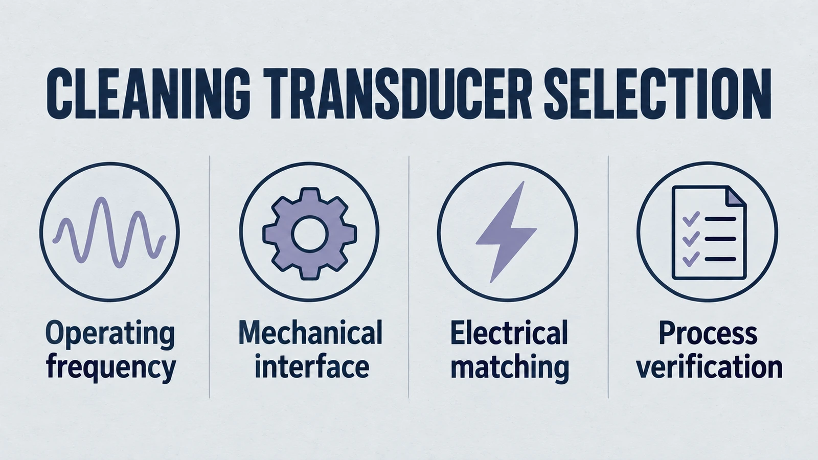
For equipment production or replenishment, use the bulk ultrasonic cleaning transducer RFQ guide to organize model, mounting and quantity information for a quotation.
The Engineer's Guide to Transducer Selection
In high-precision manufacturing, the performance of your cleaning line often comes down to one component: the ultrasonic cleaner transducer. For system integrators and process engineers, selecting this device isn't just a procurement task—it's a critical engineering decision that balances acoustic physics, material science, and chemical compatibility. A mismatch here doesn't just mean poor cleaning; it leads to substrate damage, frequency drift, and premature line failure.
This technical guide cuts through the marketing noise to focus on what matters: the engineering fundamentals of ultrasonic cleaner transducers. We’re moving beyond standard datasheet specs to explore the real-world implications of "Hard" vs. "Soft" piezoceramics, the mechanics of cavitation bubble collapse, and the structural integrity required for industrial tank bonding.
Product path for this search intent
Match the article topic to the right YJ Piezo product page
Use this article when the choice is not just a shape, but a material tradeoff between sensitivity, loss, coupling, stability, and operating field. For "Choosing the Right Ultrasonic Cleaner Transducer for Your Application: The Comprehensiv...", the practical value is in turning the topic into a measurable selection or sourcing decision.
- PZT Material Hub
Material grades and application tradeoffs
- Piezoelectric Ceramics
Shapes and ceramic manufacturing options
- PZT Material Supplier Hub
Material control, grade selection, and sourcing support
Yujie Piezo supports cleaning-transducer projects with piezoelectric manufacturing experience built since 1996. In this post, we’ll break down why specific models suit different operating envelopes and how to evaluate frequency selection (28 kHz vs. 40 kHz vs. 80 kHz), mounting, tank construction, and power density.
1. The Physics: What Actually Happens Inside the Tank?
To pick the right ultrasonic cleaner transducer, we need to understand the event it initiates. The transducer isn't just vibrating; it's an energy converter acting as the catalyst for violent, microscopic events. The efficiency of this conversion—from high-frequency electrical voltage into mechanical kinetic energy—is what separates a "humming" tank from a cleaning powerhouse.
1.1 The Mechanism of Acoustic Cavitation
The primary mechanism of ultrasonic cleaning is cavitation, the rapid formation and collapse of microscopic gas- and vapor-containing cavities within a liquid medium. When an ultrasonic cleaner transducer is bonded to a tank and driven by a generator, it creates longitudinal sound waves that propagate through the cleaning fluid. These waves consist of alternating phases of compression (high pressure) and rarefaction (low pressure).
Acoustic rarefaction can grow pre-existing gas/vapor nuclei. Whether they oscillate stably or collapse inertially depends on pressure amplitude, frequency, liquid, dissolved gas, temperature and boundaries.
Rectified diffusion can contribute to bubble growth, but is not a prerequisite for every collapse. The Minnaert relation estimates small-amplitude resonance from an equilibrium gas-bubble size and surrounding conditions; it is not a universal maximum-radius or collapse-threshold formula.
Bubble collapse can produce localized pressure, heating and microjets that contribute to soil removal. Their magnitude and duration depend on the acoustic field and liquid conditions; fixed nanosecond, temperature and pressure values are not universal cleaning specifications or bulk-bath temperatures.
1.2 The Role of the Transducer in Cavitation Dynamics
The ultrasonic cleaner transducer is the "heart" that pumps this acoustic energy into the system. Its specifications directly dictate the nature of the cavitation field:
- Resonant Frequency: This determines the maximum size of the cavitation bubble before collapse. Lower frequencies (e.g., 28 kHz) produce larger bubbles with higher implosion energy (more violent cleaning). Higher frequencies (e.g., 80 kHz) produce smaller bubbles with lower energy but higher population density (gentler, more penetrating cleaning).
- Amplitude (Displacement): This determines the intensity of the pressure wave. A transducer with a high electromechanical coupling factor (k33) and high displacement (measured in microns) will create a deeper vacuum during rarefaction, initiating cavitation more readily and in more viscous fluids.
- Beam Pattern: The shape of the transducer's radiating head (conical vs. flat) influences how the sound waves distribute in the tank. A poorly designed transducer creates "hot spots" of intense cavitation and "dead zones" of no activity. Yujie Piezo engineers transducers with specific beam widths (e.g., 6° for the HJ-2112.1M model) to optimize this distribution.
1.3 The Piezoelectric Effect: The Conversion Engine
Modern ultrasonic cleaner transducers rely on the piezoelectric effect, specifically the inverse piezoelectric effect, where an applied electric field causes a mechanical deformation in a crystal lattice. Unlike legacy magnetostrictive transducers, which utilized the magnetic expansion of nickel or ferrite cores, piezoelectric transducers use Lead Zirconate Titanate (PZT) ceramics.
PZT-based transducers often offer higher conversion efficiency than magnetostrictive types in comparable cleaning systems. High-quality piezoelectric transducers like those from Yujie can reduce generator strain, limit unnecessary heat transfer to the cleaning bath, and support a more compact, lightweight installation when the tank and generator are tuned correctly.
The crystal lattice of the PZT ceramic consists of ions that are displaced when a voltage is applied. In a poled ceramic, the domains are aligned such that a voltage of one polarity causes expansion along the poling axis, and the opposite polarity causes contraction. By driving the ceramic with a sinusoidal AC voltage at its resonant frequency, the ceramic expands and contracts thousands of times per second. This microscopic motion is then amplified by the mechanical stack of the transducer to create the macroscopic vibration needed for cleaning.
2. Anatomy of a High-Performance Yujie Transducer
To the untrained eye, an ultrasonic cleaner transducer appears to be a simple assembly of metal and ceramic. However, it is a precision-engineered resonant device known as a Langevin bolting stack. Every dimension, material choice, and interface torque is calculated to ensure the assembly resonates as a single unit with minimal internal loss. Yujie Piezo's manufacturing process controls these variables strictly to ensure batch-to-batch consistency.
2.1 The Piezoceramic Stack (The Active Element)
The core of the transducer comprises typically two or four rings of piezoelectric ceramic. These rings are the engine of the device.
- Polarization: The rings are arranged with opposing polarity facing each other (e.g., positive to positive) with a thin electrode (usually beryllium copper or nickel) in between. This parallel wiring configuration allows the stack to be driven at manageable voltages while producing the displacement of the sum of the rings.
- Diameter and Power: The diameter of the ceramic rings correlates directly with power handling. Yujie offers transducers with ceramic diameters typically ranging from 25mm to 60mm. A larger diameter ceramic provides a larger capacitance (C0) and lower impedance (Zr), allowing it to draw more current from the generator and drive larger loads. For example, the CN2850-68LB model utilizes a 50mm diameter ceramic stack to deliver high-power 28 kHz cleaning.
2.2 The Front Mass (The Radiating Head)
The front mass is the component that interfaces with the tank or the liquid. It acts as an acoustic matching layer.
- Material Selection: Aluminum is the most common material for cleaning transducers due to its acoustic impedance (Z), which is closer to water than steel or brass. This similarity allows for efficient energy transfer from the transducer into the liquid. For aggressive chemical environments or heavy-duty industrial applications, titanium alloys may be used for their superior erosion resistance and fatigue strength, though at a higher cost.
- Geometry: The shape of the front mass determines the radiation pattern.
- Trumpet/Flared (L-Type): Broadens the radiating area, distributing the energy over a wider zone on the tank wall. This reduces the risk of creating intense "hot spots" that could erode the tank.
- Cylindrical (H-Type): Provides a more focused beam.
- Threaded Interface: Many Yujie models (e.g., with suffix "B") feature a threaded hole or stud in the front mass to facilitate secure mechanical mounting to the tank, in addition to adhesive bonding.
2.3 The Back Mass (The Reflector)
The back mass is typically made of steel or a dense tungsten alloy.
- Function: Its primary role is to act as an inertial mass. Because it is much heavier and denser than the front mass, it forces the majority of the vibrational energy to propagate forward into the front mass and the tank. It essentially acts as a "backstop" for the vibration.
- Nodal Point: The design is balanced so that the nodal point (the point of zero displacement but maximum stress) falls within the ceramic stack or near the mounting flange. This minimizes energy leakage into the mounting hardware.
2.4 The Pre-Stress Bolt
A high-tensile steel bolt runs through the center of the stack, clamping the front and back masses together.
- The Physics of Pre-Stress: Ceramics are brittle materials with high compressive strength but very low tensile strength. During the rarefaction phase of vibration, the transducer attempts to elongate, which would put the ceramic in tension. If the ceramic enters tension, it can crack or depolarlize.
- Assembly Criticality: The bolt applies a massive static compressive force (pre-stress) to the ceramics. This bias ensures that even at maximum vibration amplitude, the ceramics never leave the compressive regime. Yujie Piezo employs precision torque-controlled assembly and automated aging processes to ensure this pre-stress remains stable over the transducer's lifespan.
3. Material Science: The PZT-4 vs. PZT-8 Decision
Perhaps the most critical, yet often overlooked, specification when choosing an ultrasonic cleaner transducer is the grade of piezoelectric ceramic used. Not all "PZT" is created equal. PZT-4 (Navy Type I) and PZT-8 (Navy Type III) are both hard PZT families used for power ultrasonics; PZT-5A and PZT-5H are common soft PZT families. For the discerning engineer, understanding this distinction is vital for ensuring system longevity and thermal stability.
3.1 PZT-4 (Navy Type I): A Hard Ceramic for Power Ultrasonics
PZT-4 is often characterized by a high piezoelectric charge constant (d33) and a moderate mechanical quality factor (Qm).
- Advantages: PZT-4-family hard ceramics are used in power ultrasonic and sonar applications. Compare coupling, displacement, losses, and temperature behavior at the intended drive level.
- Continuous-Duty Considerations: Both PZT-4 and PZT-8 can be suitable for cleaning transducers. PZT-8-family materials are often selected for higher drive and lower losses, but neither family alone guarantees acceptable temperature rise; validate the grade, preload, cooling, and duty cycle.
3.2 PZT-8 (Navy Type III): The "Hard" Ceramic for Power Ultrasonics
PZT-8 is engineered with dopants (acceptor ions) that "pin" the domain walls, reducing domain-wall mobility and supporting low-loss behavior under suitable drive conditions. It features a high mechanical quality factor (Qm) and very low dielectric loss (tan δ).
- Thermal Stability: PZT-8 generates significantly less internal heat during operation compared to PZT-4. This is the paramount feature for ultrasonic cleaning. A cooler transducer is a more stable transducer.
- High-Power Handling: Because of its low losses, PZT-8 can be driven at much higher electric fields without reaching thermal saturation. It maintains its piezoelectric properties and frequency stability even under heavy loads and high drive levels.
- Selecting for Cleaning Duty: Review the grade and complete ultrasonic cleaner transducer under its intended continuous-wave or intermittent load. Suitable PZT-4-family and PZT-8-family grades are used in power ultrasonics. Thermal runaway depends on losses, generator control, loading, and cooling; material designation alone does not prevent it.
3.3 The Yujie Approach: Integrated Material Control
Unlike assemblers who purchase generic ceramic rings, Yujie Piezo manufactures its own PZT powders and ceramics. This vertical integration allows us to strictly control the doping process. We don't just hope for a good batch; we engineer the material to meet specific Qm and temperature stability targets. This control extends to customizing the ceramic dimensions for specific impedance requirements, which is a game-changer for OEM generator manufacturers trying to perfectly match their drive circuits.
4. Frequency Selection: The Primary Application Variable
After material suitability and assembled-transducer performance have been validated, the next engineering decision is frequency. The resonant frequency of the ultrasonic cleaner transducer dictates the physics of the cavitation bubble and, consequently, the cleaning action. It is a trade-off between physical force and microscopic penetration.
4.1 Low Frequency: 20 kHz – 30 kHz (The "Sledgehammer")
Low-frequency cleaning often produces more aggressive cavitation, but frequency alone does not establish equilibrium or maximum bubble diameter, cleaning effectiveness or damage risk.
- Bubble Dynamics: These large bubbles store a significant amount of potential energy during their growth phase. When they implode, they release massive shockwaves and high-velocity micro-jets.
- Target Application: Ideally suited for "gross" cleaning. This includes the removal of heavy grease, baked-on carbon deposits, thick oils, and rust from robust parts like engine blocks, injection molds, and heavy steel machinery.
- Yujie Models: The CN2850 and CN2538 series (28 kHz and 25 kHz) are the workhorses here. Their large stack design supports the high power needed to drive these massive waves.
- Risk Factor: The violence of low-frequency cavitation can cause cavitation erosion (pitting) on the tank walls and on soft metals like aluminum or brass. It is generally not suitable for polished surfaces, electronics, or delicate optics.
4.2 Medium Frequency: 40 kHz (A Common Cleaning Frequency)
40 kHz is a common cleaning frequency; choose the actual frequency using soil-removal and part-compatibility tests, rather than an unsupported share of all applications.
- Bubble Dynamics: Acoustic pressure, gas content, liquid and boundaries determine bubble response. Validate removal and damage risk; 40 kHz does not guarantee a particular bubble size or universal material compatibility.
- Target Application: General precision cleaning, machined parts, medical and dental instruments, electroplating pre-treatment, and robust electronics.
- Yujie Models: The HJ-4012 and CN4025 series are our most popular units. They provide thorough cleaning coverage, penetrating blind holes and complex geometries better than 28 kHz due to shorter wavelengths.
- Standing Waves: Higher frequency reduces wavelength and standing-wave spacing, but does not by itself make the field uniform. Validate spatial cleaning coverage under the actual tank loading.
4.3 High Frequency: 80 kHz – 120 kHz+ (The "Scalpel")
As frequency increases, bubble size decreases, and the density of cavitation events increases.
- Bubble Dynamics: Higher frequency changes bubble dynamics; size, collapse severity and event density remain dependent on pressure, gas and liquid conditions.
- Target Application: Precision optics (lenses with delicate anti-reflective coatings), semiconductor wafers, hard drive components, and intricate jewelry. High frequencies are essential for removing sub-micron particles (less than 1 micron) which larger bubbles might simply push around rather than lift.
- Yujie Models: Yujie offers specific high-frequency transducers (e.g., 80 kHz, 100 kHz) and dual-frequency models that can switch between ranges.
- Penetration: High frequencies are capable of penetrating extremely small crevices, capillary tubes, and complex MEMS structures that lower frequencies cannot reach.
4.4 Megasonic Cleaning (1 MHz)
For the ultimate in delicacy, such as semiconductor wafer processing where even 80 kHz cavitation could damage nanometer-scale transistors, Yujie provides megasonic transducers (e.g., HJ-2112.1M running at 1.0 MHz).
- Mechanism: At megasonic frequencies, acoustic streaming and bubble-related microstreaming/cavitation can both contribute to particle removal. Stable and inertial cavitation depend on the field, gas and operating conditions; megasonic operation does not guarantee damage-free cleaning.
- Application: Silicon wafers, flat panel displays, and photovoltaic cells.
4.5 Multi-Frequency Systems
Modern advanced cleaning systems often utilize multi-frequency generators. A tank might start with 40 kHz to remove heavy soil and then switch to 80 kHz for a final precision rinse. Yujie Piezo manufactures wide-bandwidth transducers capable of operating effectively across a designated range or at harmonic intervals to support these sophisticated cleaning protocols.
5. Power Density and Tank Engineering
Selecting the ultrasonic cleaner transducer model is only half the battle; determining the quantity and placement is equally vital. This is governed by the concept of power density, typically measured in Watts per Gallon (W/gal) or Watts per Liter (W/L).
5.1 Calculating Power Requirements
The relationship between tank volume and required power is nonlinear. Small tanks have a high surface-area-to-volume ratio, meaning much of the acoustic energy is absorbed by the tank walls. Large tanks are more efficient at retaining energy in the bulk fluid.
- Small Tanks (< 20 Liters): Require high power density, typically 50-100 Watts/Gallon (approx. 13-26 Watts/Liter).
- Medium Tanks (20 - 100 Liters): Typically require 25-50 Watts/Gallon (approx. 7-13 Watts/Liter).
- Large Industrial Tanks (> 200 Liters): Can operate effectively with 10-25 Watts/Gallon (approx. 3-7 Watts/Liter).
| Tank Class | Volume (Gal) | Volume (Lit) | Power Density (W/gal) | Power Density (W/L) |
|---|---|---|---|---|
| Lab/Benchtop | 0.5 - 5 | 2 - 19 | 60 - 100 | 15 - 26 |
| Mid-Sized Industrial | 5 - 25 | 19 - 95 | 40 - 60 | 10 - 15 |
| Large Industrial | 25 - 100 | 95 - 380 | 25 - 40 | 6 - 10 |
| Massive | > 100 | > 380 | 15 - 25 | 4 - 6 |
Preliminary numerical sizing examples, not a cited universal standard. Define electrical input, generator output and measured acoustic output separately; use one consistent power basis and validate the loaded tank. The ranges above are not validated acceptance limits.
5.2 Transducer Count Calculation
Let us assume an engineer is designing a 100-Liter (26.4 US-gallon) tank for general automotive cleaning (requiring moderate power).
- Target Density: Select 40 W/US gal (about 10.6 W/L), as a hypothetical sizing assumption.
- Total Power: 26.4 gal × 40 W/gal = 1056 Watts.
- Transducer Selection: Choose the Yujie CN4025-45HB (40 kHz, 60 Watts).
- Count: 1056 W / 60 W = 17.6, only if both ratings have the same defined power basis; nominal component watts do not establish delivered bath power.
- Engineering Adjustment: Round up to an even number for symmetric layout, likely 18 or 20 transducers.
5.3 Loading and Shadowing Factors
The calculation above applies to an empty tank. Real-world applications involve baskets of parts.
- Mass Load: Parts and baskets change absorption, scattering and the field. Validate required power with the intended loading and cleaning outcome; a fixed 20–30% uplift is not a universal rule.
- Shadowing: Ultrasound creates "shadows" behind solid objects. If parts are densely packed in a basket, the inner parts will not be cleaned. While increasing power helps, the better solution is often to use bottom-mounted transducers combined with side-mounted transducers to create a multi-directional field. Yujie supplies submersible transducer boxes specifically for retrofitting side-wall ultrasonics into existing tanks.
6. Electrical Integration: Impedance Matching
An ultrasonic cleaner transducer is an electrical load with complex characteristics. It is essentially a capacitor in parallel with a mechanical resonant branch (the Van Dyke equivalent circuit). To get maximum power transfer from the ultrasonic generator to the transducer, their impedances must be matched.
6.1 Capacitance (C0) Considerations
Every Yujie transducer has a specified static capacitance. For example, a 28 kHz model might have a capacitance of 3800 pF ±10%, while a 40 kHz model might have 3100 pF.
- Parallel Wiring: In a cleaning tank, transducers are typically wired in parallel arrays. The total capacitance sums up (Ctotal = C1 + C2 + ...).
- Generator Tuning: The ultrasonic generator has an output transformer and a matching inductor. This inductor is tuned to resonate with the total capacitance of the transducer array at the operating frequency. If the capacitance is off (e.g., due to mixing batches of transducers or poor manufacturing consistency), the generator will not be able to deliver its full rated power.
- Yujie Consistency: Yujie Piezo’s automated manufacturing ensures tight capacitance tolerances (±5% or better), making it easier for generator manufacturers to tune their systems and ensuring that replacement banks match the original specifications.
6.2 Impedance at Resonance (Zr)
The impedance minimum near series resonance depends on geometry, connection, coupling, loading and losses; it need not coincide exactly with zero phase. A lower value alone does not establish greater electro-acoustic efficiency.
- Spec Check: Compare impedance/phase spectra against a validated reference for the exact geometry, assembly and conditions. Diagnose anomalies with output and thermal measurements; high impedance alone does not prove cracked ceramic or poor bonding.
7. Integration Engineering: The Bonding Process
The finest ultrasonic cleaner transducer in the world is useless if it is not correctly coupled to the cleaning tank. The bond interface is the single most common point of failure in ultrasonic systems. It must withstand high-frequency fatigue, thermal cycling (expansion/contraction of the tank), and chemical attack.
7.1 Adhesive Bonding (Epoxy)
Epoxy bonding is the standard industry method. However, "hardware store epoxy" will fail in minutes.
- Epoxy Selection: Yujie recommends using specialized high-modulus, high-temperature aerospace-grade epoxies. The epoxy must be hard enough to transmit the high-frequency vibration without dampening it (soft epoxies act as shock absorbers, killing the ultrasound).
- Layer Thickness: Use the validated adhesive and tank/transducer suppliers’ bond-line thickness, preparation and cure specification. Ensure complete wetting without voids or adhesive starvation; a universal metal-to-metal glue-line target is inappropriate.
7.2 Stud Welding (Mechanical Assist)
Relying solely on epoxy is risky for heavy-duty industrial tanks. The "Hybrid Method" is the gold standard.
- Stud Welding: A threaded stainless steel stud is welded to the tank surface using a capacitive discharge welder. This ensures no burn-through or distortion of the tank wall.
- Epoxy Application: The specialized epoxy is applied to the transducer face.
- Torquing: Use the specified torque for the exact stud, joint, tank and assembly. A bolt-size example does not establish a validated torque for another design.
- Why Hybrid? The stud provides the mechanical holding force and keeps the transducer under compression against the tank. The epoxy acts as the "acoustic couplant" (liquid shim) to ensure 100% surface contact for energy transfer. Without the stud, the epoxy might eventually peel due to the shear forces of the vibration. Without the epoxy, the microscopic air gaps between the transducer and tank would block the ultrasound (air is a perfect reflector of ultrasound).
7.3 Surface Preparation
The tank surface must be prepared to a clean, flat, and repeatable bonding condition.
- Sandblasting: The bonding area should be sandblasted to create a matte texture. This increases the surface area for the epoxy to grip.
- Cleaning: The surface must be degreased with extreme rigor (often using acetone or similar solvents) to remove any trace of oil, fingerprints, or dust. Even a fingerprint can cause a bond failure (delamination) which leads to a "dead" transducer and eventually a blown generator channel.
8. Durability and Failure Modes
Understanding how transducers fail helps in selecting the right one to prevent it.
8.1 Thermal Depolarization
Curie temperature is a transition, not an assembly operating limit. Depoling and drift depend on grade, field, stress, temperature and duration, and can occur below Tc; adhesives and other parts can impose lower limits. Use qualified operating limits and dry-running protection.
- Prevention: Use Yujie PZT-8 transducers (high thermal stability) and ensure liquid level sensors are installed in the tank to prevent dry-running.
8.2 Cavitation Erosion
The same force that cleans parts also attacks the tank. Over time, the stainless steel tank face will pit and erode.
- Erosion Mechanism: The violent implosion of bubbles work-hardens and then fatigues the steel grain structure, causing microscopic flakes to break off.
- Transducer Impact: Eventually, erosion can wear through the tank. But before that, the roughened surface alters the acoustic impedance matching, reducing cleaning efficiency.
- Hard Chrome: For high-intensity 28 kHz systems, Yujie recommends using tanks with Hard Chrome plating on the diaphragm face to extend service life.
8.3 Electrode Delamination
In cheap transducers, the metal electrodes between the ceramic rings can crack or delaminate due to the constant vibration. Yujie uses high-fatigue-strength beryllium copper alloys and optimized electrode geometries to prevent this mechanical fatigue.
9. Industry-Specific Selection Guide
To crystallize the selection process, we provide specific recommendations for key industries served by Yujie Piezo.
9.1 Automotive Remanufacturing
- Challenge: Heavy carbon deposits on valves, cylinder heads, grease on transmission cases.
- Recommendation: Yujie CN2850 Series (28 kHz).
- Reasoning: High amplitude is required to physically break the bond of burnt-on carbon. 40 kHz is often too gentle. The large 50mm stack handles the high power density needed for large steel tanks.
9.2 Medical Instrument Cleaning Before Disinfection or Sterilization
- Challenge: Bio-burden removal from hinged instruments, lumens, and cannulas. Must not damage cutting edges.
- Recommendation: Yujie HJ-4012 Series (40 kHz) or Dual Frequency (40/80 kHz).
- Reasoning: Ultrasonic cleaning removes soil but does not itself establish disinfection or sterilization. Validate frequency, chemistry, loading and cycle according to the instrument and equipment manufacturers’ reprocessing instructions; 40 kHz is not a universal validated medical standard.
9.3 Optics and Photonics
- Challenge: Cleaning polishing paste (cerium oxide) from glass lenses without scratching soft IR coatings.
- Recommendation: Yujie 80 kHz or 120 kHz Transducers.
- Reasoning: The high frequency creates a dense "cloud" of mild cavitation. It gently lifts the sub-micron polishing particles. Lower frequencies would drive the particles into the glass, causing scratches.
9.4 PCB and Electronics
- Challenge: Removing flux residues from under BGA (Ball Grid Array) components without damaging wire bonds.
- Recommendation: Sweep Frequency 40 kHz or 80 kHz.
- Reasoning: Frequency sweep can redistribute persistent interference patterns, rather than eliminate all standing waves. Validate component compatibility under actual frequency, loading, power and exposure; higher frequency alone does not assure electronics safety.
10. Why Yujie Piezo?
Why partner with Yujie Piezo for your ultrasonic cleaner transducers? It comes down to manufacturing depth.
10.1 From Powder to Product
Most suppliers are assemblers—they buy ceramics, heads, and back masses from different vendors and glue them together. Yujie is a fundamental manufacturer. We start with raw oxide powders, milling, calcining, and sintering our own PZT ceramics. This gives us total control over the "engine" of the transducer.
- Quality Control: We control the grain size and doping. If a ceramic batch doesn't meet our Qm specs, it’s recycled—never assembled.
- Traceability: We can trace a finished transducer back to the specific powder lot, a requirement for many high-end medical and aerospace users.
10.2 True Customization
Because we own the ceramic tooling, we aren't limited to off-the-shelf sizes. If you need a low-profile transducer for a shallow tank or a specific impedance to match a legacy generator, we can adjust the ceramic formulation and stack geometry to fit. We do this for OEM partners every day.
10.3 Direct Value
By removing the middleman in the ceramic supply chain, we deliver "Navy Type III" performance at a competitive price point. You get high-end, reliable PZT-8 performance without the markup, making robust ultrasonics viable for cost-sensitive projects.
11. Final Thoughts
Selecting an ultrasonic cleaner transducer defines your system's potential. It's the foundation of the entire process.
- Frequency is your primary variable (28 kHz for heavy lifting, 40 kHz for general purpose, 80 kHz+ for precision).
- Material matters—stick to PZT-8 for industrial reliability.
- Power Density must be calculated, not guessed.
- The Bond is critical—don't cut corners on epoxy or stud welding.
At Yujie Piezo, we see ourselves as your technical partners in the "physics of clean." Whether you're building a new line or retrofitting an existing one, our engineers are ready to help you navigate these choices.
Need a specific transducer configuration?
Reach out to our engineering team to discuss your application parameters, request detailed datasheets, or spec out a custom design. Let's build a system that works.
Talk to an EngineerRelated Technical Resources
Use these internal references to compare geometry, material selection, reliability testing, and sourcing decisions.
- Selecting Piezo Ceramics for Continuous Duty Applications
- Common Mistakes Integrating Ultrasonic Transducers into OEM Systems
- Piezoelectric Ceramics Geometry and Shape Guide
- Understanding Ultrasonic Transducers: Types and Uses
- How to Test and Measure Piezoelectric Materials
- Understanding Piezoelectric Constants d33, k, and Qm
- Ensuring Quality of Piezoelectric Components
- Troubleshooting Piezo Devices: Common Failures and Prevention
Engineering decision notes
PZT material and ceramic selection
Use this article when the choice is not just a shape, but a material tradeoff between sensitivity, loss, coupling, stability, and operating field. For "Choosing the Right Ultrasonic Cleaner Transducer for Your Application: The Comprehensiv...", the practical value is in turning the topic into a measurable selection or sourcing decision.
YJ Piezo coordinates PZT ceramic projects with manufacturing support, so material formulation, sintering, polarization, electrode process, and outgoing inspection can be reviewed against the final application.
Selection checks
- Separate sensing needs from high-power actuation needs before comparing d33 or coupling values.
- Check dielectric loss, Qm, Curie temperature, aging behavior, and operating field against the real duty cycle.
- Confirm whether the application needs standard PZT grades or a custom formulation and geometry.
Failure risks
- Choosing only the highest d33 can create heat, drift, or depolarization risk in power ultrasonics.
- A ceramic that performs well in free measurement can fail once bonded, clamped, or loaded.
- Material substitutions without batch testing can change capacitance, resonance, and system tuning.
RFQ details
- Is the part used for sensing, actuation, atomization, cleaning, welding, or measurement?
- What field strength, temperature, duty cycle, and mechanical load will the ceramic see?
- Which values must be controlled: d33, capacitance, resonance, impedance, Qm, or dimensional tolerance?
Relevant YJ Piezo pages
- PZT Material Hub
Material grades and application tradeoffs
- Piezoelectric Ceramics
Shapes and ceramic manufacturing options
- PZT Material Supplier Hub
Material control, grade selection, and sourcing support
Application FAQ
- Is the highest d33 always the best PZT choice?
- No. High d33 can be useful for sensitivity, but high-power ultrasonic systems often need lower loss, higher Qm, better thermal stability, and safer operation under field and stress.
- What makes PZT material selection different from catalog buying?
- The right PZT choice depends on geometry, load, drive field, duty cycle, temperature, and inspection targets. A catalog value is only useful when it is tied to the final assembly conditions.