
How Does a Bowl-Shaped Piezo Ceramic Focus Ultrasound?
Audience: engineers and technical readers who understand ultrasonics but want a clearer physical explanation.
Goal: explain focusing using geometry-based reasoning rather than heavy mathematics, with honest limitations.
The idea in one sentence
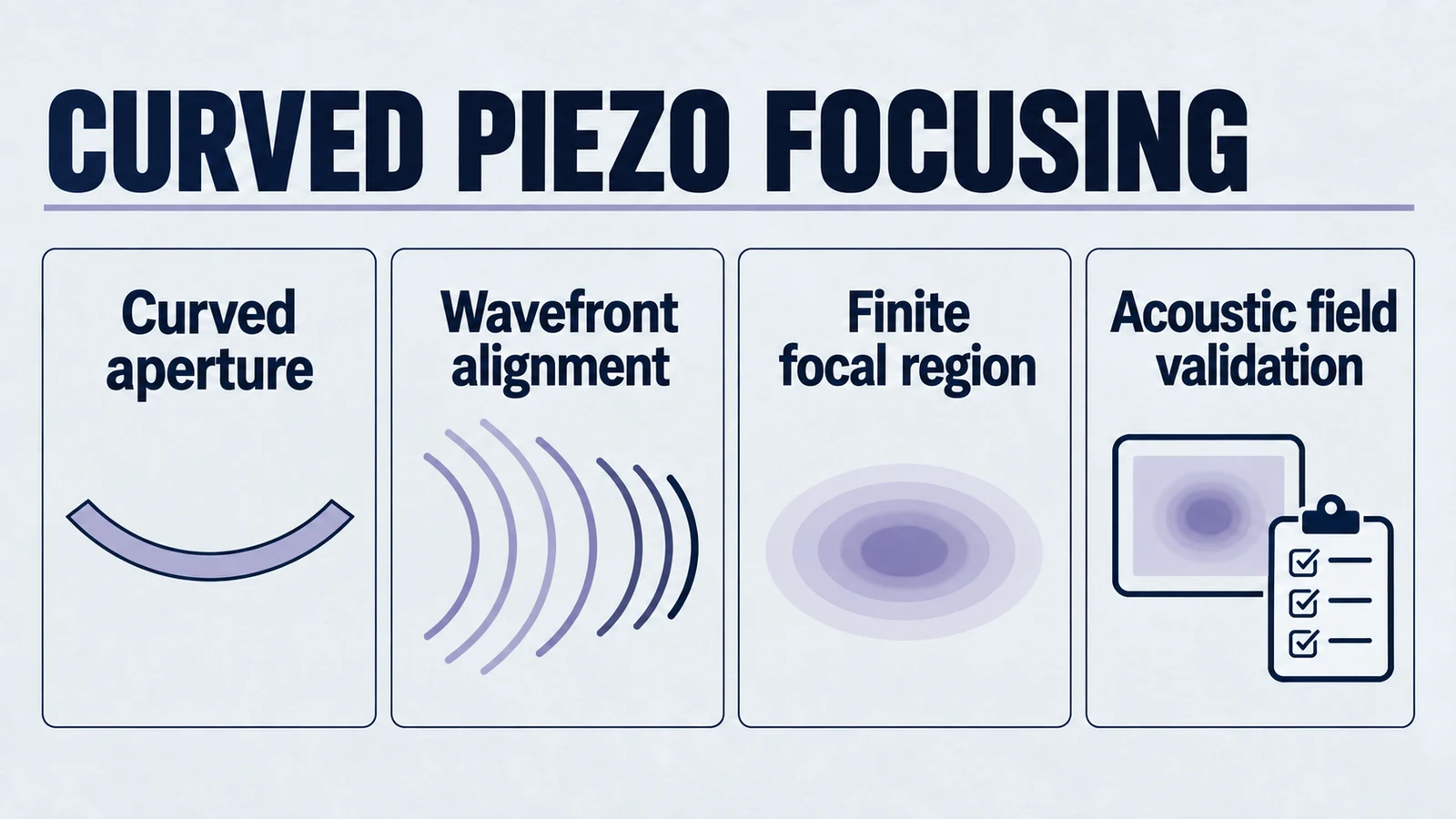
A custom spherical-cap piezo ceramic focuses ultrasound because it launches a curved wavefront whose timing is naturally “pre-aligned” by geometry. Many parts of the radiating surface send pressure cycles that arrive at a specific region in space close enough in phase that they add coherently. Outside that region, the arrivals are less aligned, so they add less efficiently and the field looks more spread.
That is the whole story. Everything else is the fine print that makes it accurate, and useful.
Product path for this search intent
Match the article topic to the right YJ Piezo product page
Use this article when the choice is not just a shape, but a material tradeoff between sensitivity, loss, coupling, stability, and operating field. For "How Does a Bowl-Shaped Piezo Ceramic Focus Ultrasound?", the practical value is in turning the topic into a measurable selection or sourcing decision.
- PZT Material Hub
Material grades and application tradeoffs
- Piezoelectric Ceramics
Shapes and ceramic manufacturing options
- PZT Material Supplier Hub
Material control, grade selection, and sourcing support
Use this article when a focused curved part is already on the shortlist: if you are still comparing focused bowls against discs, rings, tubes, rectangular plates, or other shape families, start with the broader geometry selection guide. Then come back here for the focusing mechanism itself.
1) Start with the boring reference case. A flat disk
A flat piezo disk bonded to a backing and driven with a uniform voltage behaves like a near-uniform “piston.” In the simplest mental model:
- Every point on the face moves up and down with (roughly) the same phase.
- The launched wavefront is initially planar right in front of the face.
- As it propagates, diffraction causes it to spread. The beam has a finite near field (Fresnel zone) with on-axis maxima and minima, then transitions toward a far field where the beam diverges more smoothly.
Even without doing any math, the key point is this.
A flat source does not contain any built-in “arrival-time shaping.” Its geometry does not intentionally steer energy toward a particular point in space. So it cannot strongly concentrate energy into a tight spot the way a lens, a phased array, or a curved radiator can.
A subtle but important nuance
A flat disk can show a strong on-axis maximum at a particular distance in its near field. That maximum sometimes gets casually labeled a “focus.” But physically it is not the same thing.
- It is a diffraction pattern feature caused by interference from a finite aperture.
- Its location and strength can shift strongly with frequency and with the exact vibrating area.
- It is typically broader, and less controllable, than the focal zone produced by a deliberately curved wavefront.
This distinction matters because it prevents the common mistake of expecting a flat element to behave like a focused one just because the near field contains a bright region.
2) What changes when the ceramic is bowl-shaped
A bowl-shaped ceramic is still being driven electrically. Often it is still driven approximately uniformly. The difference is the position and orientation of each radiating patch of ceramic in space.
Because the surface is a concave segment of a sphere (or close to it), every small patch on that surface is at a slightly different distance to points in front of the transducer. In other words, geometry introduces a pattern of path lengths.
Now imagine you pick one special point in space. The point that lies on the axis of the bowl, some distance in front of it.
- If that point sits near the geometric center of curvature, the distances from many surface patches to that point are similar.
- Similar distances imply similar travel times through the medium.
- When the ceramic oscillates, the pressure cycles from many patches arrive at that point with nearly the same phase.
So pressure sums constructively at that location. Energy density rises there. That is focusing.
You can think of the bowl’s geometry as “baking in” the same kind of phase delay that an acoustic lens or a phased array would otherwise need to create. The bowl does not need electronics to impose phase shifts. The surface shape makes the wavefront itself curved at launch.
A useful mental picture
Think in terms of wavefronts, not rays.
- A flat disk launches a wavefront that starts flat and then becomes complicated because diffraction and aperture edges create spatial phase variations.
- An ideal spherical radiating surface has equal paths to its center of curvature in front. Its converging field is analogous to the time-reversed diverging field of a point source at that focus.
A curved wavefront tends to converge as it propagates, just like a spherical wave can converge toward a region when the curvature is the “right way around.” But remember. We are talking about wavefields, not perfect ray bundles.
What “bowl-shaped” usually means in engineering drawings
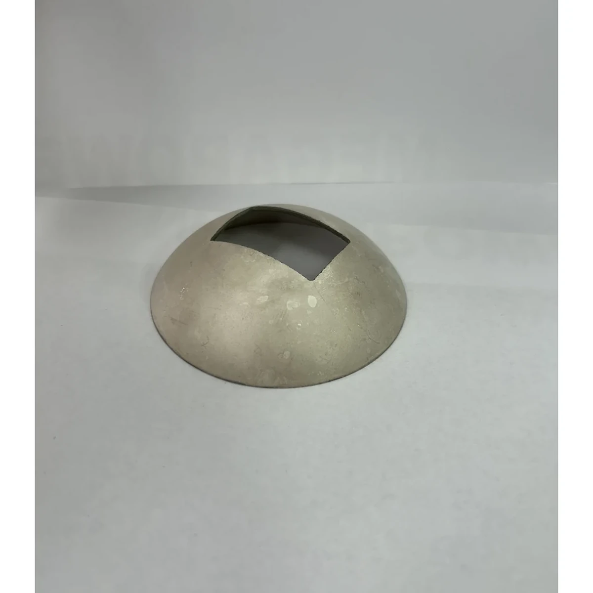
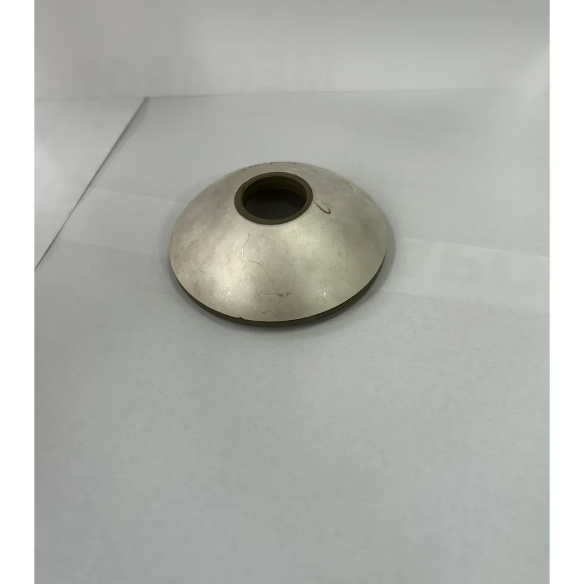
Most focused ceramics are custom spherical-cap piezo ceramics, not hemispheres. The cap’s radius of curvature, aperture diameter, and cap depth together determine the geometric tendency to converge. A shallow cap yields a longer focal distance and a less aggressive numerical aperture. A deeper cap yields stronger convergence but can be harder to match acoustically and to manufacture consistently.
3) Wavefront curvature and phase alignment (without equations)
Phase alignment is really just a timing statement.
- Ultrasound is periodic. One “cycle” is one period.
- If two contributions arrive half a cycle apart, they cancel strongly.
- If they arrive in-step, they add.
A bowl-shaped radiator is not magic. It simply arranges path lengths so that, at one region in space, many contributions are close enough in timing that they add rather than cancel.
This is why focusing is fundamentally geometric.
- Material choice affects efficiency, bandwidth, loss, and how much drive you can survive.
- Geometry determines whether the field wants to converge in the first place.
What “close enough” means in practice
Perfect phase alignment is not required to get a useful focus. A real focal zone is created when a significant fraction of the aperture contributes with phase errors small enough that the pressure still adds mostly constructively.
This is also why tiny geometric or assembly errors can be benign in some designs and severe in others. If your wavelength is large compared with the errors, phase stays reasonably aligned. If your wavelength is small, the same physical error represents a much larger fraction of a cycle.
Important limitation
Uniform drive on a curved surface does not by itself confirm perfect phase uniformity everywhere on the face.
Real ceramics have:
- finite thickness and thickness-mode behavior
- edge constraints and mounting stresses
- backing, adhesive layers, and matching-layer effects
- local variations in poling, density, and stiffness
These can perturb the phase and amplitude across the aperture. The focusing still happens. It is just not the mathematically perfect “spherical radiator” you might sketch on a whiteboard.
4) Optical focusing analogy. Helpful, but don’t overtrust it
It is tempting to say: “A bowl-shaped transducer is like a concave mirror or a lens.”
That analogy is useful for intuition because it emphasizes phase alignment. But you must keep the differences straight, or the analogy will quietly insert wrong assumptions.
Where the optics analogy works
- Both optics and acoustics can be described as wavefields.
- Constructive interference and phase alignment determine where energy concentrates.
- A curved element can create a converging wavefront.
If you want one conservative sentence. A focused transducer is closer to wave optics than to geometric optics.
Where it breaks or misleads
- Most ultrasonic fields are not well described by rays.
Rays are a high-frequency approximation. Ultrasound in fluids often has wavelengths that are not tiny compared to aperture sizes or focal dimensions. Diffraction and sidelobes matter. If you picture only rays, you will predict a cleaner, tighter focus than you can actually achieve. - The medium matters more.
Sound speed and attenuation depend strongly on the medium and temperature. In optics, you often ignore attenuation in air over small distances. In ultrasonics, attenuation, scattering, and microbubbles can dominate quickly and reshape the effective focal field. - Boundaries and impedance mismatch are central.
Lenses, matching layers, housings, and coupling layers can distort the wavefront, generate reflections, and alter effective aperture. In practice, the “optical element” is not just the ceramic shape. It is the entire acoustic stack. - Nonlinear effects can appear at high intensity.
At sufficiently high acoustic pressure, the waveform distorts. Harmonics appear. The field is no longer a simple linear superposition of one frequency component. Optics has nonlinear regimes too, but industrial ultrasonics often encounters nonlinear propagation sooner than people expect.
So yes. Think “wave focusing like optics,” but remember it is wave optics in a lossy, impedance-mismatched world with real packaging and real power.
5) Why the focal region is not a point. Focal zones are finite
Engineers often say “the focus” as if it were a dot. In reality you get a focal zone. You also get sidelobes. If you do not plan for sidelobes, they will show up in your measurements and make you doubt your model.
There are two reasons.
Reason A. The aperture is finite
A finite radiator cannot concentrate energy into an infinitesimal point.
Even in the ideal case of a perfectly shaped spherical cap with perfect phase uniformity, you still have a diffraction-limited spot. The result is:
- a main lobe (the tight central high-intensity region)
- side lobes (lower-intensity rings or off-axis features)
This is not a defect. It is a consequence of forming a converging field with a finite aperture.
A useful intuition. The aperture is the “amount of wavefront you can shape.” The larger that shaped wavefront is relative to the wavelength, the more tightly you can concentrate energy.
Reason B. The phase alignment is only “good enough” over a region
A spherical cap can only perfectly align phase to one idealized point in a simplified model.
In practice:
- the wave is not emitted from an infinitely thin surface
- the driving phase and amplitude vary across the aperture
- matching layers and housings introduce additional phase delays
- edge regions often radiate differently than the central area
So the energy builds over a region where the timing is close enough for constructive interference. Outside it, phase begins to slip and the field transitions into a more divergent pattern.
Depth of focus is part of the story
The focal zone has both a transverse size (spot width) and an axial size (how long the high-intensity region extends along the beam). Designs that produce an extremely tight spot often shorten the depth of focus. Designs that produce a longer focal zone usually trade away spot tightness.
That trade is not a marketing statement. It is simply the wave nature of a finite aperture.
6) Why focusing is frequency-dependent
If you change frequency while keeping the same geometry, the focus changes. Two physical mechanisms explain this.
Mechanism A. Wavelength sets how “picky” phase alignment is
Phase alignment is judged relative to wavelength.
- At higher frequency (shorter wavelength), a small path-length error corresponds to a larger phase error.
- That makes the field more sensitive to curvature errors, surface roughness, adhesive thickness variation, and misalignment.
So higher frequency can give you a tighter spot in principle, but it demands higher precision in geometry and in wavefront integrity.
Mechanism B. Diffraction changes with wavelength
The size of the focal spot and the depth of focus depend on the ratio of aperture size to wavelength.
- Larger aperture relative to wavelength. stronger focusing, narrower beam
- Smaller aperture relative to wavelength. weaker focusing, broader focal region
This is why “same bowl, different frequency” does not produce the same focal zone. It is also why a focused element can look impressively sharp in water at one frequency band and disappointingly broad when driven off-band.
Practical note engineers care about
Frequency is rarely independent of everything else.
- Ceramic thickness sets the thickness-mode resonance range.
- Matching layers are often designed around a target frequency band.
- Coupling layers and standoffs can introduce resonances and phase distortions.
- Attenuation in many media rises with frequency, so the usable focus depth can shrink.
So yes, focus depends on frequency. But the system constraints also force frequency choices that then feed back into achievable focus and practical range.
7) Near field, far field, and the special case of focused elements
For flat radiators, engineers often talk about a near field (Fresnel zone) where the field pattern is complex, and a far field where it becomes smoother and diverging.
A focused element complicates this language because it intentionally creates a converging field inside what would otherwise be called “near field.” If you use the flat-disk vocabulary too literally, you can end up arguing about definitions instead of designing hardware.
A more reliable way to think is:
- The bowl shape sets a geometric convergence tendency.
- Diffraction and finite aperture set the minimum spot size and sidelobes.
- The medium and packaging set loss and distortion.
If you remember those three, you will not get trapped arguing about whether the focus is “in the near field.” It is. But that is not the useful design handle.
A design-level takeaway
A focused element is best understood as a wavefront-shaping radiator, not as a flat radiator with a special near-field point. That mindset keeps your expectations aligned with measurements.
8) What determines the focus location in practice
In an ideal drawing, the focus is related to the curvature radius of the bowl. In real designs, the effective focus depends on multiple layers and boundary conditions.
It is helpful to separate “geometric focus tendency” from “system focus outcome.” The ceramic sets the tendency. The stack decides the outcome.
Factors that shift or blur the focus
- Curvature accuracy of the ceramic face.
- Aperture diameter (how much of the spherical surface is present).
- Matching layers (thickness and sound speed) which add phase delay.
- Adhesive layers (often overlooked) which can add non-uniform phase delay if thickness varies.
- Coupling layer (water path, gel layer, standoff) which changes the acoustic path.
- Housing and baffle geometry which can clip or reshape the aperture.
- Temperature (sound speed shifts, material property shifts, and impedance changes).
The practical takeaway is simple: the bowl gives you a strong starting point, but the focus is a system property, not a ceramic-only property.
9) A grounded intuition check. How to sanity-test your mental model
If your explanation is correct, it should predict these qualitative behaviors.
- If you flip the bowl (make it convex), the focus disappears.
A convex surface tends to launch a diverging wavefront. You get defocusing, not focusing. - If you reduce the aperture while keeping curvature, the focus gets weaker and the spot grows.
Smaller effective aperture means diffraction dominates more, so the field cannot concentrate as tightly. - If you raise frequency (within the usable band), the spot can tighten, but alignment becomes more sensitive.
Shorter wavelength improves potential resolution but punishes phase errors, manufacturing tolerance, and stack-induced phase distortion. - If you add an acoustically imperfect standoff or lens, you can ruin a good ceramic focus.
Because you have introduced extra phase distortion, reflections, and potential trapped modes. - If you change coupling medium, the focus can shift and the peak can drop.
Sound speed and attenuation change. The same geometry produces a different phase accumulation in a different medium.
If a narrative can’t predict these, it is probably an analogy doing too much work.
10) Common misconceptions to avoid
Misconception 1. “A focused ceramic concentrates energy into a mathematical point”
No. You get a finite focal zone with sidelobes. The field is wave-limited.
Misconception 2. “Focusing is mainly about PZT material type”
Material matters for efficiency, bandwidth, power handling, and loss. But focusing is primarily geometric. A high-k material does not create focus if the wavefront is not shaped.
Misconception 3. “The measured acoustic maximum always equals the geometric focus”
The ideal sphere’s center of curvature is exactly R from the emitting vertex. The measured acoustic pressure or intensity maximum can differ because of finite-aperture diffraction, loading, layers and propagation. State the reference surface and distinguish geometric focus from acoustic maximum.
Misconception 4. “Higher frequency always means better focus”
Higher frequency can reduce spot size, but it also increases attenuation and sensitivity to wavefront errors. There is always a trade.
Misconception 5. “If it’s focused, sidelobes don’t matter”
Sidelobes are not optional. They can produce unintended heating or detection artifacts. If your application is sensitive, you must account for them in measurement and design.
Practical conclusion
A bowl-shaped piezo ceramic focuses ultrasound because its concave geometry launches a wavefront with built-in curvature. That curvature aligns phase at a region in front of the transducer, so pressure sums coherently there instead of spreading.
The focus is not a point because the radiator is finite and the wave nature of sound imposes diffraction limits. The focal zone depends on frequency because wavelength sets both diffraction behavior and how sensitive phase alignment is to imperfections.
If you keep those three ideas straight. Geometry shapes the wavefront. Phase alignment creates concentration. Wavelength sets the limits. You will have an intuition that stays honest when real hardware shows up.
If you’re designing a focused element, the next engineering questions are usually: what aperture-to-wavelength ratio do you have, what coupling path and matching layers distort phase, what adhesive and housing details quietly add phase errors, and what thermal and mechanical constraints limit drive level. Those system-level factors decide whether the theoretical focus becomes a useful, stable focus in production.
Engineering decision notes
PZT material and ceramic selection
Use this article when the choice is not just a shape, but a material tradeoff between sensitivity, loss, coupling, stability, and operating field. For "How Does a Bowl-Shaped Piezo Ceramic Focus Ultrasound?", the practical value is in turning the topic into a measurable selection or sourcing decision.
YJ Piezo coordinates PZT ceramic projects with manufacturing support, so material formulation, sintering, polarization, electrode process, and outgoing inspection can be reviewed against the final application.
Selection checks
- Separate sensing needs from high-power actuation needs before comparing d33 or coupling values.
- Check dielectric loss, Qm, Curie temperature, aging behavior, and operating field against the real duty cycle.
- Confirm whether the application needs standard PZT grades or a custom formulation and geometry.
Failure risks
- Choosing only the highest d33 can create heat, drift, or depolarization risk in power ultrasonics.
- A ceramic that performs well in free measurement can fail once bonded, clamped, or loaded.
- Material substitutions without batch testing can change capacitance, resonance, and system tuning.
RFQ details
- Is the part used for sensing, actuation, atomization, cleaning, welding, or measurement?
- What field strength, temperature, duty cycle, and mechanical load will the ceramic see?
- Which values must be controlled: d33, capacitance, resonance, impedance, Qm, or dimensional tolerance?
Relevant YJ Piezo pages
- PZT Material Hub
Material grades and application tradeoffs
- Piezoelectric Ceramics
Shapes and ceramic manufacturing options
- PZT Material Supplier Hub
Material control, grade selection, and sourcing support
Application FAQ
- Is the highest d33 always the best PZT choice?
- No. High d33 can be useful for sensitivity, but high-power ultrasonic systems often need lower loss, higher Qm, better thermal stability, and safer operation under field and stress.
- What makes PZT material selection different from catalog buying?
- The right PZT choice depends on geometry, load, drive field, duty cycle, temperature, and inspection targets. A catalog value is only useful when it is tied to the final assembly conditions.