
Mode Coupling in Piezo Ceramics: When Geometry Becomes a Risk
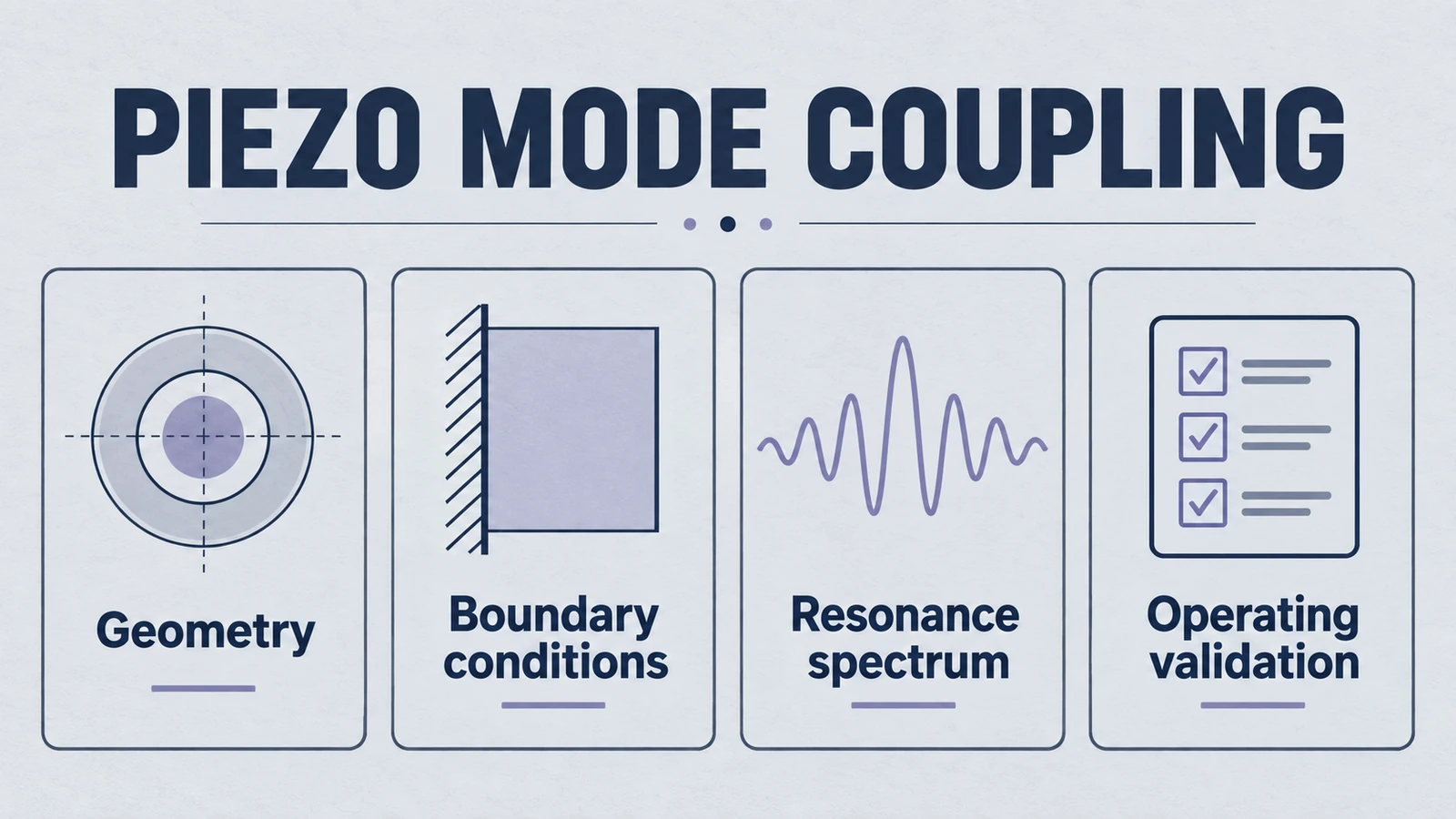
1. The clean vibration you wanted, and the extra vibration you accidentally built
Most engineers start with a reasonable mental model.
- Apply voltage.
- The ceramic changes thickness.
- The surface moves like a piston.
- The transducer outputs a predictable acoustic field.
That model works only when one mode dominates. The moment your geometry makes two resonant families comparable in frequency and coupling strength, your “simple actuator” becomes a multi-mode resonator.
Product path for this search intent
Match the article topic to the right YJ Piezo product page
Use this article when the choice is not just a shape, but a material tradeoff between sensitivity, loss, coupling, stability, and operating field. For "Mode Coupling in Piezo Ceramics: When Geometry Becomes a Risk", the practical value is in turning the topic into a measurable selection or sourcing decision.
- PZT Material Hub
Material grades and application tradeoffs
- Piezoelectric Ceramics
Shapes and ceramic manufacturing options
- PZT Material Supplier Hub
Material control, grade selection, and sourcing support
That is mode coupling.
Mode coupling is not just “two peaks in impedance”. It is the situation where:
- Two vibration modes are close enough in frequency to interact.
- The structure cannot support them independently.
- Energy injected into the intended mode leaks into an unintended mode.
If you are designing for stability, efficiency, and repeatability, coupling is an engineering risk because it changes the system from “predictable” to “sensitive”.
2. The two main competitors. Thickness mode vs radial modes
For common piezo geometries like discs, rings, plates, tubes, and hollow spheres, the most common conflict is:
- Thickness (longitudinal) mode: motion primarily through the thickness direction. Often the desired mode for ultrasound generation.
- Radial (planar) modes: in-plane expansion and contraction. Often unintended, but inevitable.
This conflict exists because the material is not a one-axis machine.
2.1 Why radial motion exists even when you drive thickness
A piezoelectric ceramic has coupled constitutive behavior. When you apply an electric field in the poling direction (often thickness), you get strain in multiple directions.
In simplified form:
- is thickness strain.
- , are in-plane strains.
- is typically negative for PZT. That means thickness expansion is accompanied by in-plane contraction, and vice versa.
So even if your electrodes are perfect and your drive is perfectly normal to the surface, the material tries to move radially.
If your geometry gives that radial motion a resonant path, it will take it.
2.2 The “mode chart” intuition
A disc has two primary geometric length scales:
- Thickness ()
- Diameter ()
Each length scale supports its own resonance family.
A rough intuition is:
- is a thickness-mode frequency scale.
- is a radial-mode frequency scale.
- , are effective acoustic velocities for those mode families (material and boundary dependent).
As changes, these mode families sweep past each other.
When a radial mode lands near the thickness resonance, coupling becomes likely.
3. The dangerous zone. Aspect ratio thresholds (D/T)
Engineers often discover mode coupling too late because they treat “frequency” as a single number.
But for a finite ceramic body, you have a forest of modes.
The most common early warning metric is the aspect ratio:
For disc-like elements, coupling risk rises when puts a strong radial mode close to the operating thickness-mode resonance.
3.1 Practical threshold behavior
There is no universal magic number because boundary conditions matter.
- free vs bonded
- single disc vs stack
- backing and matching layers
- electrode pattern and mass loading
- preload and housing constraints
But the design reality is consistent.
- Small diameter-to-thickness ratio: A long slender geometry approaches a longitudinal rod model, with k33 rather than the laterally clamped thin-plate kt limit. Select the model for the relevant mode and boundary conditions.
- Intermediate : radial and thickness modes approach. Coupling risk climbs quickly.
- Large diameter-to-thickness ratio: A thin disc can approach a useful thickness-mode model over a selected band, while finite-boundary and higher modes remain. Increasing the ratio does not universally destroy one-dimensional thickness behavior.
A useful engineering posture is to treat mid-range aspect ratios as a risk zone.
If your design sits there, you should assume coupling until you prove otherwise.
3.2 The avoided crossing. Why modes don’t simply “pass through”
In an ideal mathematical world, two uncoupled resonance curves cross.
In real piezo structures, when two modes interact they often show an avoided crossing:
- the resonant peaks repel each other,
- the mode shapes become mixed,
- and both resonances become partially “wrong” for your intended function.
This is why coupling is not a minor spectral detail.
It reshapes the operating physics.
4. What coupling does to performance. Instability, inefficiency, and surprises
Coupling is a failure mechanism generator.
Not always immediate severe failure. Often it is “why does this design behave differently between samples”.
4.1 Electrical signatures
In impedance or admittance measurements, coupling may show up as:
- split resonant peaks
- unexpected anti-resonance locations
- multiple local minima
- temperature-sensitive drift beyond expectation
- a strong change when you alter mounting torque or adhesive thickness
If your prototype only “works” when clamped a specific way, coupling is a suspect.
4.2 Acoustic field signatures
For ultrasonic sensors and transducers used in underwater, cleaning, welding, and acoustic applications, coupling may produce:
- beam pattern distortion
- unexpected side lobes
- unstable amplitude vs frequency tuning
- higher near-field clutter
- angle-dependent sensitivity that wasn’t predicted
This is especially dangerous in systems that assume a clean piston radiator.
4.3 Mechanical consequences
The most expensive consequence is not an ugly frequency response.
It is stress.
Coupled modes often create localized bending and tensile regions, particularly near:
- edges of discs and rings
- electrode boundaries
- interfaces with adhesives or metal caps
- geometric discontinuities and machining marks
Piezo ceramics are strong in compression and brittle in tension.
If coupling introduces tensile stress where you expected mostly compressive cycling, the fracture risk rises.
5. Fracture risk. How “the wrong mode” breaks a ceramic
Ceramics fail when the stress state and defect population align.
Mode coupling increases risk by creating:
- Mixed stress states: thickness mode plus radial mode can create bending.
- Edge amplification: radial modes often concentrate strain near the perimeter.
- Interface stress: bonding layers see shear and peel components.
- Thermal sensitivity: a small temperature shift can move resonance alignment, changing stress distribution.
A common surprise is a design that survives at low drive but cracks at high drive, even though average displacement seems reasonable.
That is often a sign that local stress is being driven by an unintended mode.
6. Why mode coupling is overlooked in early design
If mode coupling is so common, why do teams miss it.
Because early design workflows reward simplicity.
6.1 Early selection bias. “Pick frequency, then pick thickness”
A frequent workflow is:
- choose target frequency
- choose thickness from the thickness-mode formula
- choose diameter for power handling or assembly constraints
That seems logical, but it treats diameter as mechanically passive.
It is not.
Diameter creates its own resonant physics.
6.2 Over-reliance on 1D models
Many quick calculators assume one-dimensional thickness vibration.
These are useful, but only when the geometry supports 1D behavior.
As soon as grows, the 1D assumption becomes an optimistic fiction.
6.3 Prototype validation that hides the problem
Mode coupling can be masked by:
- heavy backing that damps radial modes
- thick adhesive layers
- preload that shifts boundary conditions
- test fixtures that accidentally constrain the part
Then the problem returns when you change the assembly.
If the part only behaves in the lab jig, it is not robust.
7. A failure-oriented design checklist. How to treat coupling as a risk to eliminate
This is not about perfect prediction. It is about not being surprised.
7.1 Start with a coupling risk hypothesis
If your disc-like element has a moderate or high , assume coupling risk.
Write it down as a design hazard.
That changes behavior.
It forces the team to validate it early.
7.2 Use impedance plus mode-shape validation
Impedance alone can mislead.
Two peaks do not tell you which mode is which.
Pair it with at least one of:
- laser vibrometry
- scanning interferometry
- finite element modal analysis
- experimental holography
You need to see the surface motion.
A “clean” thickness mode should show near-uniform phase across the active surface, not a patchwork.
7.3 Stress is the real metric at high power
If your application is high-drive ultrasound, displacement is not enough.
Track stress hotspots.
If a coupled mode creates tensile stress near edges or interfaces, your lifetime will be set by those hotspots.
7.4 Geometry choices that reduce coupling likelihood
Without turning this into a geometry catalog, the general direction is:
- avoid aspect ratios where strong radial modes sit near your operating thickness resonance
- reduce sharp discontinuities that amplify local strain
- manage boundary conditions deliberately (bonding, preload, support)
- keep electrode and mechanical symmetry when you need clean axisymmetric behavior
The point is not “always make D/T small”. The point is “do not treat D/T as a cosmetic parameter”.
8. What to do when you cannot avoid the risk zone
Sometimes constraints force you into a coupling-prone geometry.
Then your goal shifts from avoidance to control.
Approaches include:
- damping strategies (backing, lossy layers)
- boundary condition engineering (preload, compliant mounts)
- frequency planning (operate away from the mixed region)
- geometry segmentation (arrays, rings, partitioning)
But be honest.
If your operating band sits where modes are mixed, tuning will be fragile.
That is not a manufacturing issue. It is physics.
9. Summary. Geometry is not packaging, it is a resonator design decision
Mode coupling is what happens when your geometry allows two vibration families to compete.
Thickness mode and radial modes are natural rivals in piezo ceramics.
Aspect ratio () is the simplest early warning indicator, but boundaries and assembly decide the exact outcome.
When coupling occurs, it can cause:
- unstable resonance behavior
- distorted acoustic fields
- efficiency losses
- and, most importantly, stress states that raise fracture risk
If you want robust designs, treat geometry as a first-class risk variable.
Do not wait until late prototypes to discover that your “simple disc” is actually two oscillators arguing inside a brittle material.
If you are evaluating a new piezo geometry for a transducer, document the intended mode, the nearest competing modes, and the stress hotspots. That one page often prevents the most expensive surprise: a design that only works when everything is exactly perfect.
Engineering decision notes
PZT material and ceramic selection
Use this article when the choice is not just a shape, but a material tradeoff between sensitivity, loss, coupling, stability, and operating field. For "Mode Coupling in Piezo Ceramics: When Geometry Becomes a Risk", the practical value is in turning the topic into a measurable selection or sourcing decision.
YJ Piezo coordinates PZT ceramic projects with manufacturing support, so material formulation, sintering, polarization, electrode process, and outgoing inspection can be reviewed against the final application.
Selection checks
- Separate sensing needs from high-power actuation needs before comparing d33 or coupling values.
- Check dielectric loss, Qm, Curie temperature, aging behavior, and operating field against the real duty cycle.
- Confirm whether the application needs standard PZT grades or a custom formulation and geometry.
Failure risks
- Choosing only the highest d33 can create heat, drift, or depolarization risk in power ultrasonics.
- A ceramic that performs well in free measurement can fail once bonded, clamped, or loaded.
- Material substitutions without batch testing can change capacitance, resonance, and system tuning.
RFQ details
- Is the part used for sensing, actuation, atomization, cleaning, welding, or measurement?
- What field strength, temperature, duty cycle, and mechanical load will the ceramic see?
- Which values must be controlled: d33, capacitance, resonance, impedance, Qm, or dimensional tolerance?
Relevant YJ Piezo pages
- PZT Material Hub
Material grades and application tradeoffs
- Piezoelectric Ceramics
Shapes and ceramic manufacturing options
- PZT Material Supplier Hub
Material control, grade selection, and sourcing support
Application FAQ
- Is the highest d33 always the best PZT choice?
- No. High d33 can be useful for sensitivity, but high-power ultrasonic systems often need lower loss, higher Qm, better thermal stability, and safer operation under field and stress.
- What makes PZT material selection different from catalog buying?
- The right PZT choice depends on geometry, load, drive field, duty cycle, temperature, and inspection targets. A catalog value is only useful when it is tied to the final assembly conditions.