
Ultrasonic Transducer Applications Guide: Cleaning, Welding, NDT, Medical, and Sensing
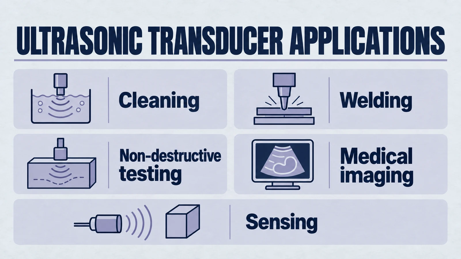
Quick answer: Ultrasonic transducers convert electrical energy into sound above 20 kHz and often convert returning sound back into electrical signals. Cleaning and welding favor power handling and low loss; NDT and medical imaging favor bandwidth, resolution, and sensitivity; sensing favors stable echo behavior in the target medium.
This page compares applications. For transducer architectures and selection trade-offs, use the separate ultrasonic transducer types guide. For material fundamentals, read what PZT is.
For product evaluation, start from the OEM transducer supplier hub, then compare cleaning, welding, or sensor families.
Introduction: Application-First Selection Framework
In our modern world, we are surrounded by technologies that rely on invisible forces. From the radio waves that carry our communications to the magnetic fields that power our electric motors, these unseen energies have become integral to our daily lives. Among the most powerful and versatile of these is ultrasound—sound waves vibrating at frequencies far beyond the range of human hearing.
This high-frequency acoustic energy allows us to perform extraordinary tasks: to visualize a new life developing in the womb, to ensure the absolute structural integrity of a critical aircraft component, and to achieve a level of microscopic cleanliness impossible by other means. At the heart of every one of these technological marvels is a single, important device: the ultrasonic transducer.
Product path for this search intent
Match the article topic to the right YJ Piezo product page
Use this article when cleaning performance depends on cavitation strength, tank coupling, frequency selection, and long-run thermal behavior. For "Ultrasonic Transducer Applications Guide: Cleaning, Welding, NDT, Medical, and Sensing", the practical value is in turning the topic into a measurable selection or sourcing decision.
- Ultrasonic Cleaning Transducers
Cleaning models for tank and precision cleaning systems
- Piezoelectric Ring Series
Ring ceramics used in high-power transducer stacks
- Piezoelectric Ceramics
PZT material and geometry options for acoustic output
An ultrasonic transducer is a device that masterfully converts one form of energy into another. Specifically, it transforms electrical energy into high-frequency sound waves (ultrasound) and, just as importantly, converts the returning sound waves back into electrical signals. This dual capability to both "speak" and "listen" in the language of ultrasound is what makes it such a powerful tool.
The elegant physical principle that enables this remarkable transformation is the piezoelectric effect, a property inherent in certain advanced materials like the PZT (Lead Zirconate Titanate) ceramics we specialize in. It is this singular phenomenon that serves as the common technological ancestor for a vast and seemingly disconnected array of high-tech applications.
This comprehensive guide explores ultrasonic transducer technology across three major applications: industrial cleaning systems, medical imaging devices, and non-destructive testing equipment.
How Ultrasonic Transducers Work: The Science Behind the Technology
To truly appreciate the applications of ultrasonic transducers, one must first understand the sophisticated interplay of physics and material science that governs their operation. A transducer is not merely a component; it is a highly integrated acoustic system where each element is meticulously engineered to generate, control, and receive sound waves with exceptional precision.
The Piezoelectric Principle: Energy Conversion at the Crystalline Level
The magic behind most modern ultrasonic transducers lies in a phenomenon known as the piezoelectric effect. In simple terms, piezoelectricity is the ability of certain crystalline materials to generate an electric charge in response to applied mechanical stress. When you squeeze or press on a piezoelectric crystal, it produces a voltage—this is the direct piezoelectric effect.
Crucially, this process is entirely reversible. When an electric field is applied to the same material, it physically changes shape—expanding or contracting slightly. This is the inverse piezoelectric effect, and it is this property that allows an ultrasonic transducer to generate sound waves. By applying a rapidly oscillating alternating current (AC) voltage, the piezoelectric material is forced to vibrate at a high frequency, creating powerful, directional ultrasound waves.
While some naturally occurring crystals exhibit this property, the vast majority of high-performance ultrasonic transducers today rely on specially formulated ceramics. Among these, Lead Zirconate Titanate (PZT) is the most widely used material due to its strong piezoelectric properties and the ability to be engineered for specific performance characteristics.
Anatomy of an Ultrasonic Transducer: Core Components
A high-performance ultrasonic transducer is a sophisticated assembly of materials, each playing a critical role in shaping the final acoustic wave. Understanding this anatomy reveals how a transducer is optimized for specific applications, from precision cleaning to medical imaging.
The Active Element
This is the heart of the ultrasonic transducer—the piezoelectric PZT ceramic or crystal that performs energy conversion. An approximately unloaded uniform thickness-mode plate can use a half-wave thickness model. Radial, flexural, shear, bonded and bolt-clamped assemblies require their own modal and loaded analysis; a half-wave plate does not describe every transducer or guarantee maximum useful output.
The Backing Material
Bonded directly to the back of the active element is a dense, highly attenuative material, often a mixture of tungsten powder and epoxy. This component absorbs sound energy that radiates backward from the crystal and quickly dampens the crystal's vibration after electrical pulse excitation, creating short, well-defined pulses essential for high-resolution applications.
The Matching Layer and Wear Plate
Applied to the front face of the ultrasonic transducer, matching layers serve as acoustic bridges. PZT crystals have very high acoustic impedance, while water, soft tissue and air have much lower impedance; metals and other solids can have different relations to PZT. Matching layers minimize reflection and maximize energy transmission into the target, dramatically improving transducer sensitivity and efficiency.
Frequency and Performance: Critical Engineering Trade-offs
One of the most fundamental concepts in ultrasonic transducer applications is the relationship between frequency, resolution, and penetration depth. The choice of transducer frequency represents a critical engineering trade-off:
High Frequency (5 MHz to 20 MHz): High-frequency ultrasonic transducers produce short wavelengths for detecting small features and creating high-resolution images, but have limited penetration depth due to faster attenuation.
Low Frequency (500 kHz to 2.5 MHz): Low-frequency ultrasonic transducers have longer wavelengths with reduced detail resolution but can penetrate much deeper, making them ideal for inspecting large, thick components in industrial NDT applications.
Application 1: Industrial Ultrasonic Cleaning Systems
While ultrasound is often associated with imaging, one of its most powerful industrial applications is cleaning. Ultrasonic cleaning systems can remove the most stubborn contaminants from intricate parts, achieving levels of cleanliness unattainable with manual scrubbing or chemical solvents alone. The secret lies in a phenomenon called acoustic cavitation.
The Science of Ultrasonic Cleaning: Acoustic Cavitation
The cleaning action in ultrasonic transducer systems is driven by acoustic cavitation—the rapid formation and violent collapse of millions of microscopic bubbles in liquid. This process unfolds in microseconds:
- An industrial ultrasonic cleaning transducer bonded to a stainless-steel tank energizes
- It vibrates at frequencies between 20 kHz and 40 kHz for industrial applications
- Intense vibration creates alternating high and low pressure waves through cleaning fluid
- During low-pressure phases, gas/vapor-containing nuclei can grow into cavitation bubbles
- In subsequent high-pressure phases, these bubbles collapse with incredible energy
- Each implosion releases powerful micro-shockwaves that blast contaminants from surfaces
Optimizing Ultrasonic Cleaning Performance
The effectiveness of ultrasonic cleaning systems depends heavily on transducer engineering and placement:
Lower Frequencies (20-40 kHz): Low-frequency ultrasonic transducers produce larger, more powerful bubbles ideal for heavy-duty cleaning of automotive engine blocks and large industrial molds.
Higher Frequencies (60-80+ kHz): Create smaller, gentler bubbles perfect for delicate items like medical instruments, electronics, and precision jewelry.
Engineers comparing handpiece options can also review the facial treatment transducer HJ-3415, the skincare device transducer HJ-7035, and the HJ-4012/1M / HJ-4012/3M skincare transducers.
Ultrasonic transducers can be permanently bonded to tanks or use immersible configurations for retrofitting existing systems. Strategic placement prevents debris interference and ensures uniform cleaning coverage.
Application 2: Medical Ultrasound Imaging Systems
Perhaps the most widely recognized application of ultrasonic transducers is in medical imaging and sonography. These systems provide safe, real-time, methods without ionizing radiation; acoustic exposure still requires appropriate clinical control to visualize internal organs, monitor fetal development, and assess blood flow, making them invaluable diagnostic tools in modern medicine.
Medical Ultrasound Principles: From Sound Waves to Images
Medical ultrasonic transducers operate on the pulse-echo principle, similar to naval sonar but engineered specifically for human body imaging:
- The transducer probe is placed on skin with water-based gel as acoustic couplant
- The probe emits short, directional high-frequency ultrasound pulses (typically 2-20 MHz)
- Sound waves encounter boundaries between different tissue types and reflect back as echoes
- The same piezoelectric elements detect returning echoes, converting mechanical pressure to electrical signals
- Advanced processing systems create real-time images from thousands of pulse-echo cycles per second
Modern Medical Transducer Arrays
Modern medical probes are sophisticated ultrasonic transducer arrays that may contain tens to hundreds of elements in conventional 1D designs, or thousands in 2D matrix arrays. Element count and layout depend on architecture. Such arrays use individual piezoelectric elements arranged side-by-side. This array architecture enables electronic beamforming without physical probe movement:
Transducer Array Types:
- Linear Arrays: Straight-line elements producing rectangular images, ideal for superficial structures like thyroid and vascular imaging
- Convex Arrays: Curved element arrangement creating fan-shaped fields for abdominal and obstetric applications
- Phased Arrays: Small footprint designs using complex timing delays for cardiac examinations through rib spaces
device-level Applications Beyond Imaging
Ultrasonic transducer applications in medicine extend beyond diagnostic imaging to device-level interventions:
Lithotripsy: High-energy ultrasonic transducers generate focused shock waves that pulverize kidney stones into passable fragments, offering non-invasive alternatives to surgical procedures.
focused ultrasound systems: Validated focused ultrasound systems use focused high-power ultrasonic beams in validated device workflows. Treatment performance and safety depend on the complete device design, regulatory pathway, and validated use case.
Application 3: Non-Destructive Testing (NDT) and Quality Assurance
In critical industries like aerospace, power generation, and oil & gas, structural integrity is central to safe operation. Ultrasonic NDT transducers provide essential capabilities to inspect components for internal flaws without causing damage, helping maintenance teams identify risks before they become serious failures.
Ultrasonic Testing Fundamentals
Ultrasonic transducers in NDT detect internal discontinuities like cracks, voids, porosity, and inclusions, while performing precise thickness measurements to monitor corrosion or erosion. The pulse-echo methodology reveals exact flaw depths when sound waves reflect off internal discontinuities.
NDT Process:
- Ultrasonic transducers send short sound pulses into test components
- Sound travels through material until hitting boundaries or flaws
- Flaws create additional echoes arriving before back-wall reflections
- Echo timing reveals precise flaw depth and location
- Signal analysis determines flaw size and characteristics
Specialized NDT Transducer Types
NDT applications require various specialized ultrasonic transducer configurations:
- Contact Transducers: Rugged probes for straight-beam inspections and thickness measurements
- Angle Beam Transducers: Used with wedges for weld inspection applications at specific angles
- Immersion Transducers: Sealed units for automated water bath inspections with focused beams
- Phased Array Transducers: Multi-element arrays creating detailed cross-sectional images
Modern NDT has adopted medical imaging technologies, using phased array ultrasonic transducers with multiple elements to electronically sweep beams and create detailed component images, dramatically increasing inspection speed and reliability.
Comparative Analysis of Ultrasonic Transducer Applications
| Application Area | Core Mechanism | Frequency Range | Primary Benefits |
|---|---|---|---|
| Ultrasonic Cleaning | Acoustic Cavitation | 20 kHz - 80 kHz | High-precision, non-abrasive cleaning |
| Medical Ultrasound | Pulse-Echo Imaging | 2 MHz - 20 MHz | Real-time, non-invasive visualization |
| Non-Destructive Testing | Flaw Reflection Analysis | 0.1 MHz - 15 MHz | Internal flaw detection without damage |
This comparison demonstrates the remarkable versatility of ultrasonic transducers. Each application requires specialized piezoelectric elements engineered to meet unique acoustic demands, from microscopic cleaning bubbles to deep-penetration flaw detection.
Yujie Piezo: Your Partner in Ultrasonic Transducer Innovation
Across industrial cleaning, medical diagnostics, and non-destructive testing, ultrasonic transducer performance fundamentally depends on the quality and precision of core piezoelectric elements. Every cleaning tank's power, medical image's clarity, and NDT inspection's reliability begins with the crystalline structure of PZT ceramics inside the transducer.
As a trusted OEM partner, Yujie Piezo provides high-performance hearts for advanced ultrasonic systems. Our material science expertise and precision manufacturing ensure every PZT element delivers exact acoustic properties required for innovation in ultrasonic transducer applications.
Whether developing next-generation medical probes, automated NDT scanners, or high-efficiency industrial cleaning systems, your product's performance starts with quality piezoelectric cores. Contact our engineering team to discuss specific material properties and component designs for your ultrasonic transducer innovations.
Conclusion: The Future of Ultrasonic Transducer Technology
From the elegant physics of the piezoelectric effect to its transformative impact on modern technology, the ultrasonic transducer represents a pinnacle of human engineering ingenuity. These sophisticated devices harness high-frequency sound to clean, visualize, and safeguard our world in previously unimaginable ways.
Innovation continues advancing with flexible and wearable ultrasonic transducers promising continuous health monitoring and more integrated inspection technologies. As this future unfolds, demand for higher performance, greater precision, and unwavering reliability will continue growing. At the core will remain the resonant heart of every system—the piezoelectric transducer, quietly and powerfully shaping our technological landscape.
Ready to integrate ultrasonic transducer technology into your next innovation? Explore our comprehensive range of piezoelectric components and contact our technical experts to discuss your specific application requirements.
Application Planning Notes
Once the application paths are clear, teams usually need to connect those workflows to candidate sensor models and RFQ details.
Application-to-Model Mapping
- Automation distance control: SR55 ultrasonic sensor
- Outdoor medium-range level sensing: UltraNova-2 ultrasonic sensor
- Compact equipment integration: MRR-1 ultrasonic sensor
RFQ Checklist
- Target range and acceptable blind-zone limit.
- Environment details: dust, foam, vapor, washdown, or chemicals.
- Output interface: PNP/NPN, relay, analog, or RS485 requirements.
- Power and duty profile for continuous or intermittent operation.
- Annual quantity, sample timing, and delivery expectations.
Start model screening at the ultrasonic sensor hub, review supplier capabilities on ultrasonic transducer supplier page, and send your requirements through engineering RFQ contact.
External References
Engineering decision notes
Ultrasonic cleaning and cavitation
Use this article when cleaning performance depends on cavitation strength, tank coupling, frequency selection, and long-run thermal behavior. For "Ultrasonic Transducer Applications Guide: Cleaning, Welding, NDT, Medical, and Sensing", the practical value is in turning the topic into a measurable selection or sourcing decision.
YJ Piezo evaluates cleaning transducers by acoustic output, impedance stability, ceramic loss, bonding quality, and how the assembly couples into the tank.
Selection checks
- Choose frequency from the cleaning target, part geometry, and contamination type rather than from price alone.
- Review ceramic material, bonding area, impedance, and tank mounting as one acoustic chain.
- Ask whether the transducer is intended for intermittent cleaning, continuous industrial operation, or precision cleaning.
Failure risks
- A transducer can heat water but still produce weak useful cavitation if it is poorly matched to the tank.
- High output without thermal margin can shorten ceramic, adhesive, or cable lifetime.
- Mixing 28 kHz and 40 kHz assumptions can create poor cleaning uniformity or excessive noise.
RFQ details
- What tank size, liquid, duty cycle, and cleaning target are involved?
- Which frequency and power range are currently used or being replaced?
- Do you need impedance records, bonding guidance, or sample validation before production?
Relevant YJ Piezo pages
- Ultrasonic Cleaning Transducers
Cleaning models for tank and precision cleaning systems
- Piezoelectric Ring Series
Ring ceramics used in high-power transducer stacks
- Piezoelectric Ceramics
PZT material and geometry options for acoustic output
Application FAQ
- Why can a cleaning transducer heat liquid but clean poorly?
- Heat only proves energy is entering the system. Useful cleaning needs controlled cavitation, correct frequency, good tank coupling, and stable impedance under load.
- What should I provide for a cleaning transducer quotation?
- Provide tank dimensions, liquid type, target material, duty cycle, desired frequency, current transducer model if replacing one, and whether the system needs continuous industrial operation.