
Why a 200 kHz Ultrasonic Anemometer Can Jump After a Transducer Pair Change
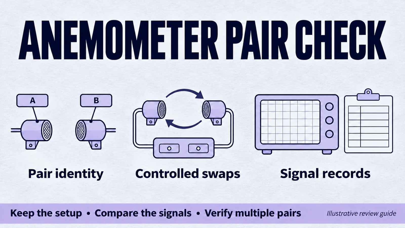
One transducer pair produces stable readings in a still-air fixture. A second pair, tested with the same firmware settings, intermittently produces large jumps. Both are nominally 200 kHz, and the processing software still reports a valid result.
For a wind-sensor OEM, this creates a purchasing question as well as a debugging question: what must be specified and evaluated so that the approved design can use recurring batches of transducers?
The starting point is a controlled comparison that preserves the waveform, configuration and component identities. A frequency label alone does not answer that question.
What the published engineering discussion actually shows
In a TI E2E discussion about an open-air anemometer prototype, the developer reported pair-dependent jumps while the algorithm returned valid results. TI's reply considered the waveform consistent with cycle slip, recommended investigating the captured signal and suggested transducer/channel exchanges.
That is evidence of a specific development problem, not a finding that every similar symptom has the same cause. The discussion concerns another manufacturer's transducers. It is neither a YJ failure report nor proof that substituting a YJ model will solve the issue.
The following investigation matrix is a proposed OEM test plan, not a reproduction of TI's test or a prescribed configuration for its software.
Identify what changes when the pair changes
Give the transducers individual identifiers and record which two form each pair. Identify their mounting positions, electrical channels and wiring. Keep the acoustic-path geometry with the record, including any reflector arrangement.
Retain the firmware revision and the excitation, gain, sampling and processing settings. Record the environmental conditions and how the still-air reference is established. If the setup changes between runs, the phrase “same settings” should not conceal a different mounting, channel or capture configuration.
Where the electronics permit, retain the received waveform in both directions together with the reported timing result and status flags. An output number without its associated capture is a limited basis for investigating an intermittent event.
Use a swap matrix to separate possible causes
Plan each change before running it. The purpose is to distinguish hypotheses; a single swap does not automatically isolate a fault.
| Comparison | Change deliberately | Keep recorded or controlled | Question it helps investigate |
|---|---|---|---|
| Reference pair versus candidate pair | Pair identity | Geometry, electronics and processing configuration | Is the difference reproducible for those configurations? |
| Same pair on alternate channels | Channel assignment | Pair identity and documented acoustic arrangement | Does the behavior follow the pair or channel path? |
| Same electrical configuration, alternate mounting position | Mechanical location | Wiring, settings and pair identity | Is the location or installation implicated? |
| Same pair, planned excitation comparison | Approved excitation setting | Other settings and operating conditions | How does the received waveform change? |
| Same pair, planned receive-setting comparison | One defined receive setting | Excitation and physical arrangement | Does the setting improve the candidate without degrading other cases? |
| Several pairs under the proposed production setup | Pair membership | Shared setup and acceptance criteria | Is one common configuration suitable for the evaluated sample population? |
Observe the approved voltage, duty and operating limits throughout the evaluation. Frequency or gain adjustments should be part of a recorded test, not an undocumented attempt to make one troublesome pair pass.
Define an event before counting it
Decide how the test will identify a discontinuity or other unacceptable result. Preserve raw data and distinguish the event criterion from the software's success flag. Record the number of measurements and the duration of the run, together with any excluded data and the reason for exclusion.
A brief run without an observed event is useful evidence for that run. It does not establish that the event rate is zero across production or operating conditions. Choose further test duration, sample coverage and environmental conditions from the device requirements.
If a configuration improves one pair, return to the reference and other candidate pairs. An OEM needs to know whether the adjustment supports a shared production setup or introduces a need for per-unit characterization. Record that decision before specifying the production acceptance process.

Use the YJ model as a candidate with defined limits
YJ's HJ-FS-200-02A ultrasonic anemometer transducer is listed for airflow and wind-sensing assemblies. Its current catalog page lists a resonance frequency of 200 kHz ±4% and static capacitance of 400 pF ±20%.
These values describe catalog characteristics of the component. They do not specify pair-selection limits, a finished instrument's wind-speed accuracy or compatibility with a particular signal-processing library. Review the complete model information and the intended acoustic/electrical arrangement before choosing evaluation parts.
If you require selected pairs, waveform characterization or additional inspection records, identify them as requested quotation items. Their scope and acceptance criteria need project-specific confirmation.
Turn the investigation into an OEM supply request
Discuss your anemometer transducer project with YJ Piezo. Include the acoustic-path drawing, direct or reflective geometry, transducers per instrument and proposed pairing arrangement.
Share the drive and receive settings, relevant environmental range, representative captures in both directions and a concise description of any observed jumps. State whether your production plan requires one shared configuration or allows individual characterization.
Add the number of evaluation pairs, intended production order size and expected annual demand in pairs or individual transducers. Keeping the units explicit avoids a simple commercial ambiguity when each instrument contains several acoustic paths.
The objective is an agreed component and evaluation scope that your team can connect to instrument qualification. The final wind-measurement performance still needs validation in the complete OEM design.
Related Products
Related Guides
Discuss Your Anemometer Transducer Evaluation
Send the acoustic arrangement, drive and receive settings, required evaluation pairs and expected annual demand.
Request an Anemometer Supply Review