
Ultrasonic Flow Transducer Pair Qualification: Zero-Flow and Temperature Test Planning
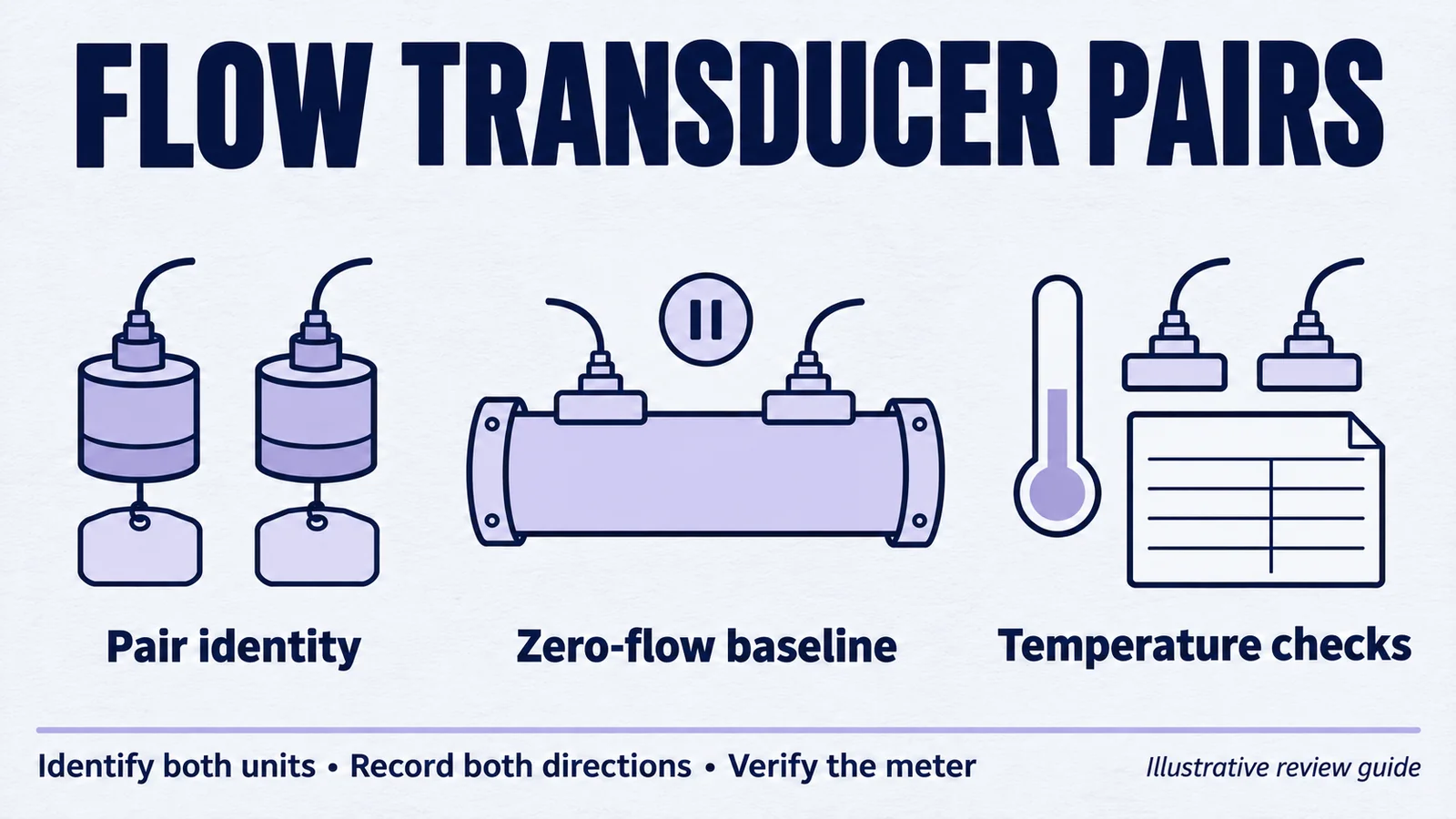
For a transit-time flowmeter, buying two transducers with the same nominal frequency is the beginning of a selection process. The relevant purchasing decision is whether the proposed pair works in the meter's acoustic path, with its electronics and calibration method.
A qualification plan should connect the identity of each transducer to measurements in both directions. It should also state what a zero-flow result means and which temperature conditions the OEM needs to evaluate.
This article provides a proposed test-planning record. It does not set meter-accuracy limits or claim that a particular YJ transducer has already passed your application's qualification.
Define the acoustic path and the supply boundary
In the inquiry, identify whether you need a transducer component, a defined pair or a finished sensing module. Provide the meter-body drawing or a shareable sketch showing the acoustic path, mounting interfaces and fluid contact. Specify the liquid, temperature and pressure conditions for the project.
Do not infer clamp-on suitability, chemical compatibility or finished-meter accuracy from a frequency label. Those requirements need their own review.
Use catalog values to identify candidates
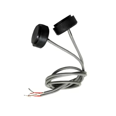
YJ lists both the HJ-2112/1M and HJ-2825/1M in its liquid-flow transducer range. Their current product pages list a nominal frequency of 1.0 MHz with a ±5% tolerance and static capacitance of 1200 pF ±20%.
Those shared entries are catalog reference points. They are not evidence that the models are interchangeable or that any two units form an application-qualified pair. Review the complete model specifications, interfaces and test conditions before choosing samples.
If you need the supplier to select pairs against an additional criterion, request that service explicitly. The method, limits and associated records must be confirmed in the quotation.
Establish a zero-flow baseline
Identify both transducers and their installed positions. Record the electronics configuration, drive waveform, receive settings and method used to derive the reported result. Where the development system permits it, retain the underlying captures in both directions as well as the calculated output.
Define how the test fixture establishes zero flow. A closed valve label alone does not document the fluid's actual state. Record stabilization conditions and distinguish raw measurements from values after calibration or compensation.
A reported offset is a system observation. Before assigning it to a transducer, investigate the test fixture, acoustic path, electronics and processing configuration. The test should allow the team to separate these possibilities rather than assuming a cause from the first result.
Agree a temperature matrix before testing
Select test points from the intended application and the approved operating limits. State how temperature is measured and when a condition is considered stable. Where return-to-baseline behavior matters, include a return condition in the plan.
| Test condition | Configuration to identify | Results to retain | Acceptance question |
|---|---|---|---|
| Reference zero flow | Pair, positions, fluid and electronics revision | Raw/processed baseline and repeat measurements | Is the result stable under the agreed reference condition? |
| Application temperature points | Measured conditions and stabilization rule | Both-direction signals and reported zero-flow result | Does the defined configuration meet the OEM's limits? |
| Return to reference | Same pair and documented elapsed conditions | Comparison with the initial baseline | Is the behavior within the agreed return criterion? |
| Known nonzero flow | Traceable flow reference and complete meter setup | Meter output against the reference | Does the meter meet its flow-performance requirement? |
| Reinstallation, if relevant | Recorded removal and mounting procedure | New baseline and operating results | Is assembly repeatability adequate? |
Successful zero-flow testing alone does not establish accuracy across the flow range. Treat known-flow verification as a separate requirement with an appropriate reference and uncertainty assessment.
Investigate pair differences without losing the evidence
Suppose one illustrative pair passes and another does not. Preserve each pair's member identities, mounting positions and electronic settings. A planned exchange of channels or positions can help investigate the difference, but document exactly what changes.
If you adjust the processing configuration for a particular pair, retain both the original and revised settings. Decide whether the production design will permit individual configuration or require every accepted pair to meet a shared setup. That decision affects factory testing and replacement parts.
Before moving to production, specify whether approval applies to those samples, a named transducer configuration or a broader supply qualification. Keep pair-level records where your agreed process requires them, and define what happens when one member is replaced.
Request components for your meter program
Discuss your flow-transducer requirement with YJ Piezo. Send the proposed model or drawing, fluid and acoustic-path information, drive and receive conditions, temperature/pressure requirements and your acceptance plan.
Include the required sample pairs, pairs per production order and expected annual demand. Identify any requested pair selection or data reporting separately from the standard component requirements.
If some requirements are still open, share the measurements or failure condition you are trying to resolve. A review can then address a defined OEM integration question rather than an unsupported promise of overall meter accuracy.
Related Products
Related Guides
Plan a Flow Transducer Evaluation
Share the fluid, acoustic path, installation conditions, proposed pair tests and evaluation and annual quantities.
Discuss Your Flow Transducer Project