
Electrical Driving Challenges of Focused Piezo Ceramics
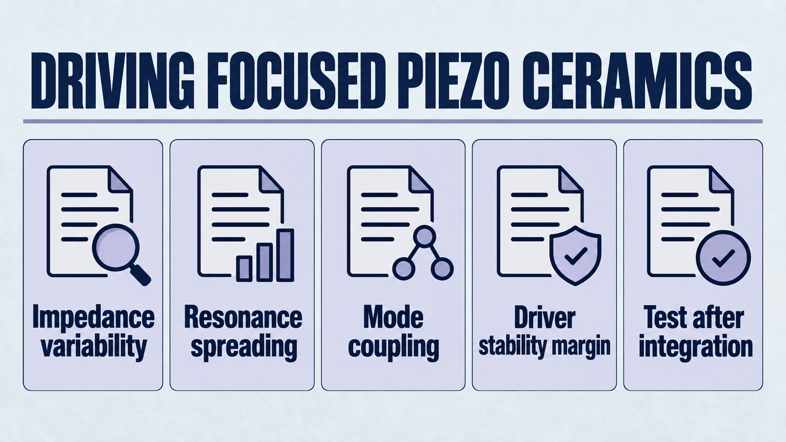
Subtitle. What system designers need to evaluate early.
Focused (spherically curved) piezoelectric ceramics can deliver compact acoustic focusing without external lenses. That geometry change looks mechanical, but it quietly reshapes the electrical problem you have to solve. If you treat a focused element like "a flat disc with a different beam pattern," you can end up with unstable drive behavior, inconsistent acoustic output, or a driver that looks fine on the bench but misbehaves in the integrated product.
This article is written for electronics engineers and ultrasonic system designers who own the driver architecture. It does not teach circuit topologies or tuning tricks. It focuses on evaluation and risk identification. The goal is to help you decide what you must characterize, how to interpret what you measure, and where focused ceramics can force conservative margins. For geometry background, see spherically curved piezoelectric ceramics.
1. Why focused geometry changes the electrical story
Product path for this search intent
Match the article topic to the right YJ Piezo product page
Use this article when the choice is not just a shape, but a material tradeoff between sensitivity, loss, coupling, stability, and operating field. For "Electrical Driving Challenges of Focused Piezo Ceramics", the practical value is in turning the topic into a measurable selection or sourcing decision.
- PZT Material Hub
Material grades and application tradeoffs
- Piezoelectric Ceramics
Shapes and ceramic manufacturing options
- PZT Material Supplier Hub
Material control, grade selection, and sourcing support
At first order, a piezo element is an electromechanical transformer. You put in voltage and current. It stores energy in a capacitance. It couples some of that energy into mechanical strain. Near resonance, that coupling becomes strong and the electrical impedance becomes sharply frequency dependent.
A focused ceramic changes several underlying assumptions:
- Stress and strain are spatially non-uniform by design. Curvature creates a geometry where the displacement field is not the same everywhere across the active area.
- Manufacturing tolerances map to resonance shifts more aggressively. Small changes in thickness, curvature radius, and edge conditions can split or broaden resonances.
- Boundary conditions are harder to reproduce. The holder, backing, adhesive line, and preload can change the effective stiffness and damping. Focused parts are often mounted in ways that add additional mechanical constraints.
The result is that the electrical input impedance that your driver sees is often less predictable than with a comparable flat element. You can still build a robust system. You just need to evaluate it like a system, not like a standalone component.
2. Focused piezo ceramic impedance. Variability and resonance spreading
2.1 The core reality. impedance is a moving target
For driver architecture decisions, it is tempting to reduce the load to "a capacitor plus a motional branch." That model is useful. But focused ceramics often violate the clean separation between a single dominant mode and everything else.
What changes in practice:
- Resonance frequency can vary more across samples. Curvature introduces another geometric degree of freedom. If thickness and curvature both vary within tolerance, their combined effect on resonance can be larger than in a flat disc where thickness dominates.
- Resonance peaks can broaden or split. Instead of one sharp minimum or maximum in impedance, you may see multiple nearby features or a wider band of elevated current draw.
- The apparent capacitance may shift with assembly. Mounting constraints and backing changes effective stiffness and loss. That can change the baseline capacitive behavior you measure at low excitation.
A practical consequence. If your driver is designed assuming a narrow, stable resonance, but the real load spreads across a frequency band, the system can drift into an unintended operating point, especially under closed-loop control.
2.2 Why resonance spreading happens in curved geometries
Focused ceramics can excite multiple mechanical patterns that are close in frequency. You can think of it as the structure having more than one plausible way to store energy and move, especially when the geometry is not perfectly symmetric.
Common contributors:
- Thickness variation around the cap. Even small gradients can lead to slightly different local resonant behavior, which shows up electrically as a broadened response.
- Edge constraints and clamping. If the rim is constrained unevenly, modes that would otherwise be degenerate can separate.
- Backing and adhesive losses. Loss and damping do not just reduce Q. They can reshape the impedance curve in ways that look like extra modes.
You do not need to solve a full finite-element model to take this seriously. You just need to treat impedance as a distribution, not a single curve. For a focused discussion, see mode coupling risk in piezo ceramics.
2.3 What to evaluate early
System designers should ask for or measure:
- Impedance magnitude and phase vs frequency across the intended operating band, not just the nominal resonance.
- Sample-to-sample spread across a meaningful lot size, not just one golden sample.
- Temperature sensitivity of resonance features and baseline capacitance.
- Excitation level dependence (small signal vs near-operating amplitude). Some behaviors only appear when the element is driven hard.
The deliverable you want is not a single f0 and Q value. It is a picture of what the driver might face across manufacturing variation and operating conditions. Measurement discipline from piezo testing and measurement workflows is useful here.
3. Mode coupling. why the driver can become unstable
3.1 What mode coupling means for electronics engineers
Mode coupling is the inconvenient truth that one mode does not live in isolation. Mechanical energy can move between patterns of motion. Electrically, that means the impedance your driver sees can change abruptly with small shifts in frequency, mounting, or loading.
In focused ceramics, coupling can show up as:
- Unexpected phase rotation near operating frequency. Your control loop may assume a predictable phase margin. Coupled modes can eat that margin.
- Sudden jumps in current at near-constant voltage. If the system drifts toward a mode with lower impedance, the driver can hit current limits.
- Multiple stable operating points. Under certain control strategies, the system may lock onto different resonance features depending on startup conditions.
None of this requires a bad design. It can happen simply because the mechanical structure offers more than one attractive resonance path.
3.2 How coupling becomes a system-level problem
A focused element rarely operates alone. It is attached to:
- a matching layer or lens-like interface (even if not a discrete lens)
- a backing or absorber
- a housing that constrains the rim
- a coupling medium whose acoustic impedance changes (water, gel, tissue, air, load fixtures)
Each of these changes boundary conditions. Boundary conditions shift mode shapes. Mode shapes shift the electrical signature.
So if you bench-test the ceramic in a fixture that is not representative, you can measure a clean impedance curve and still end up with a messy, coupled response in the assembled product. If your use case is medical-like, cross-check these constraints in focused piezo ceramics for medical ultrasound.
4. Bench testing vs integrated behavior. why it worked on the bench fails
4.1 The bench test trap
Bench measurements are usually done under conditions that are electrically convenient and mechanically simple:
- minimal or inconsistent clamping
- air loading (often effectively unloaded)
- low excitation amplitude
- short measurement time (no thermal soak)
These conditions tend to produce:
- higher apparent Q (sharper resonance)
- less damping
- less heating
- less coupling to housing modes
Your integrated product often does the opposite.
4.2 What changes when you integrate
Once assembled, you introduce:
- preload and constraint. Holder stiffness changes resonance.
- bond line effects. Adhesive thickness, modulus, and cure state add compliance and loss.
- coupling medium loading. The acoustic load adds damping and shifts resonance.
- thermal gradients. Local heating changes material constants and resonance.
- EMI and wiring parasitics. Cable inductance and stray capacitance reshape the electrical load seen by the driver.
A key point. In an integrated system, it is common for resonance to shift during operation, not just across samples. A driver designed with narrow margins can end up chasing a moving target.
4.3 What representative testing means
Early in the program, aim for measurements that approximate the final boundary conditions:
- test in a mechanically representative holder or clamp stiffness
- include the backing and bond line when possible
- measure under the intended loading medium
- test after thermal soak, not only at ambient
- characterize wiring and harness parasitics at the real cable lengths
You are not optimizing yet. You are establishing whether the electrical behavior is tame enough for your intended driver concept. This aligns with integration checks used in OEM ultrasonic programs.
5. Why some focused ceramics require conservative drive margins
If you talk to engineers who have shipped focused-ceramic systems, you will hear a recurring pattern. When uncertainty is high, they buy reliability by leaving margin.
Focused ceramics often push you toward conservative margins because:
- worst-case impedance dips can be lower than expected. that drives higher current
- mode coupling can reduce control-loop robustness. you may need to avoid operating too close to sensitive regions
- temperature and loading move resonances. your operating frequency may cross problematic features during warm-up
- aging and depoling risk increases with stress and temperature. aggressive drive conditions can accelerate drift
Conservative margin is not giving up performance. It is acknowledging that late-stage redesign is more expensive than early-stage headroom.
What conservative margins typically protect against:
- driver overcurrent and overheating
- inconsistent acoustic output over time
- field failures due to adhesive fatigue or ceramic cracking under unintended excitation patterns
- performance regression when suppliers change or tolerances shift
A practical mindset. Assume your production population will include a few electrically unfriendly units. Design so those units do not force a recall. For long-duty screening logic, see continuous-duty piezo selection considerations.
6. A system-oriented evaluation checklist
This is not a tutorial. It is a set of questions that reveal whether you have hidden electrical risk.
6.1 Load characterization
- Do you have impedance magnitude and phase vs frequency over the full operating band.
- Do you have data across multiple parts from the same lot and across lots.
- Do you understand how resonance features shift with temperature, preload, and acoustic loading.
- Do you know how the load changes at operating drive levels compared to small-signal measurements.
6.2 Driver risk exposure
- What is the worst-case current draw at your maximum voltage across expected impedance dips.
- What happens to the driver if resonance shifts during warm-up.
- How sensitive is your stability margin to phase changes near resonance.
- What parasitics does your wiring introduce, and do they create new peaks or notches.
6.3 Integration realism
- Are you testing with representative mounting stiffness and bond line conditions.
- Are you testing in the real coupling medium and with the real acoustic load.
- Are you measuring after thermal soak and at steady state, not only at startup.
6.4 Reliability and production robustness
- Do you have acceptance criteria that correlate with system performance, not just component specs.
- Can you detect bad actors electrically before assembly.
- Do you have enough margin to tolerate supplier-to-supplier variation in material constants.
If any of these are unknown late in the program, you are effectively gambling that integration will be kind to you.
7. What to communicate to your ceramic supplier early
For focused ceramics, the best procurement conversations are specific. Ask for the data that matters to the driver.
Useful requests include:
- impedance curves (magnitude and phase) with measurement conditions documented
- sample-to-sample statistics on resonance features and capacitance
- tolerance stack details on thickness, curvature radius, and rim geometry
- recommendations on mounting boundary conditions that preserve repeatability
- any known do not operate here frequency regions or mode-coupling sensitivities
Suppliers who build focused ceramics often have practical tribal knowledge about what makes parts behave badly. If you ask the right questions early, you can avoid treating that knowledge as a surprise later. You can align these requests with available custom spherical-cap piezo ceramics and piezoelectric ceramic categories.
8. Closing perspective. design the driver around uncertainty, not around a single curve
The electrical risk in focused piezo ceramics is rarely that the part is unusable. The risk is that the part is usable only under assumptions that do not survive real production and integration.
If you evaluate focused piezo ceramic impedance as a distribution, treat mode coupling as a stability risk, and insist on representative testing early, you can pick a driver architecture that survives manufacturing spread, loading changes, and thermal drift.
That is the real win. Avoiding late-stage redesigns that consume schedule and force compromises you did not budget for. If your team needs a broader electrical context, compare with piezo driver electronics and integration guidance.
FAQ for Engineering Evaluation
What is your MOQ and sample lead time for engineering evaluation?
For focused ceramic projects, engineering samples can be arranged for validation. MOQ starts from pilot quantities and depends on geometry complexity, tooling status, and test scope. Sample lead time is confirmed after reviewing your target frequency, aperture, and operating medium.
Which parameters can be customized for OEM projects?
Commonly customized items include geometry (radius of curvature, aperture, thickness), electrode layout, resonance target window, and mounting boundary recommendations. For system-level matching, teams usually define the electrical band, loading medium, and mechanical constraints together.
What are your delivery timelines and which test reports can you provide?
Delivery timelines depend on whether the design uses standard tooling or new tooling. Typical engineering support includes impedance data, resonance feature spread across samples, and agreed verification records for incoming inspection and integration checks.
Request Engineering Support
If you are evaluating focused ceramics for a new driver architecture, share your operating band, load medium, and integration constraints with our engineering team.
Related Technical Reading
Focused geometry and impedance
- Ceramic geometry vs acoustic lenses for focused ultrasonic transducer architecture
- How to choose the radius of curvature for focused piezo ceramics
- Key design parameters of spherically curved piezo elements
- Mode coupling in piezo ceramics and geometry risk
- Focused piezo ceramics for medical ultrasound engineering constraints
Driver stability and validation
- Common mistakes integrating ultrasonic transducers into OEM systems
- Selecting piezo ceramics for continuous duty applications
- How to test and measure piezoelectric materials
- Driving piezo actuators guide for driver electronics
Product and inquiry paths
Engineering decision notes
PZT material and ceramic selection
Use this article when the choice is not just a shape, but a material tradeoff between sensitivity, loss, coupling, stability, and operating field. For "Electrical Driving Challenges of Focused Piezo Ceramics", the practical value is in turning the topic into a measurable selection or sourcing decision.
YJ Piezo coordinates PZT ceramic projects with manufacturing support, so material formulation, sintering, polarization, electrode process, and outgoing inspection can be reviewed against the final application.
Selection checks
- Separate sensing needs from high-power actuation needs before comparing d33 or coupling values.
- Check dielectric loss, Qm, Curie temperature, aging behavior, and operating field against the real duty cycle.
- Confirm whether the application needs standard PZT grades or a custom formulation and geometry.
Failure risks
- Choosing only the highest d33 can create heat, drift, or depolarization risk in power ultrasonics.
- A ceramic that performs well in free measurement can fail once bonded, clamped, or loaded.
- Material substitutions without batch testing can change capacitance, resonance, and system tuning.
RFQ details
- Is the part used for sensing, actuation, atomization, cleaning, welding, or measurement?
- What field strength, temperature, duty cycle, and mechanical load will the ceramic see?
- Which values must be controlled: d33, capacitance, resonance, impedance, Qm, or dimensional tolerance?
Relevant YJ Piezo pages
- PZT Material Hub
Material grades and application tradeoffs
- Piezoelectric Ceramics
Shapes and ceramic manufacturing options
- PZT Material Supplier Hub
Material control, grade selection, and sourcing support
Application FAQ
- Is the highest d33 always the best PZT choice?
- No. High d33 can be useful for sensitivity, but high-power ultrasonic systems often need lower loss, higher Qm, better thermal stability, and safer operation under field and stress.
- What makes PZT material selection different from catalog buying?
- The right PZT choice depends on geometry, load, drive field, duty cycle, temperature, and inspection targets. A catalog value is only useful when it is tied to the final assembly conditions.