
What Are Spherically Curved Piezoelectric Ceramics? A Practical Introduction to Focused Ultrasonic Elements
Focused ultrasonics often sounds more exotic than it is. In many cases, the “secret” is not a special piezo material, a mysterious polarization trick, or a proprietary circuit. It is geometry.
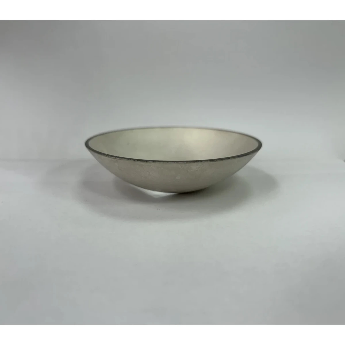
A custom spherical-cap piezo ceramic is a piezo element whose active face is a portion of a sphere. When that face vibrates in thickness mode, the acoustic wavefront leaving the surface is naturally curved. Curved wavefronts can converge to a region in front of the element. That region is the focus.
This article explains what spherical-cap piezo ceramics are, how they differ from flat discs, and what they can and cannot do in real ultrasonic systems. It is written to clear up the “mental shortcuts” engineers and technical buyers often carry from flat-piston transducer thinking.
Product path for this search intent
Match the article topic to the right YJ Piezo product page
Use this article when curved ceramic geometry, focal distance, acoustic intensity, and assembly tolerances matter more than a flat element comparison. For "What Are Spherically Curved Piezoelectric Ceramics? A Practical Introduction to Focused...", the practical value is in turning the topic into a measurable selection or sourcing decision.
- Spherical Cap Piezoelectric Ceramics
Focused ceramic shapes for OEM ultrasonic assemblies
- Piezoelectric Ceramics
Shape and material options for custom design
- Air Acoustic Transducers
Acoustic interface references for beam behavior
1. Terminology and geometry. Spherical-cap vs hemispherical
Engineers often use “curved,” “hemisphere,” and “spherical” interchangeably. That is where the confusion starts. The geometry terms are not cosmetic. They change focal distance, manufacturability, and how the element can be mounted.
1.1 Spherical-cap geometry
A custom spherical-cap piezo ceramic is a segment of a sphere cut by a plane. In practice, it looks like a shallow bowl (concave) or a shallow dome (convex).
You can fully define a spherical cap using any consistent set of parameters. Common ones are:
- Sphere radius, . Radius of the sphere the cap belongs to.
- Aperture radius, . Radius of the circular opening.
- Sag (height), . Maximum depth of the cap relative to the rim plane.
These are related by standard geometry:
If you know and , you can compute . If you know and , you can compute using:
Why OEM designers care: For a simple focusing element, in a uniform medium and ignoring refraction and aberrations, the geometric focus is approximately at distance from the concave radiating surface. So is a first-order knob for focal distance.
A second-order knob is the aperture size relative to . Two parts can share the same , but behave differently if one has a much larger aperture diameter. That difference shows up in focal spot size, sidelobes, and sensitivity to alignment.
1.2 Hemispherical geometry
A hemisphere is a special case of a spherical cap. It is exactly half of a sphere.
For a hemisphere:
That is a very deep cap. Most “focused” piezo elements used in compact transducers are not hemispheres. They are shallow spherical caps because hemispheres create mechanical, mounting, and electrode challenges, and the aperture becomes large relative to available packaging.
A practical implication is that “hemispherical” is often a sloppy label used to mean “curved.” If a drawing or spec does not state , , and , you do not actually know what geometry you are getting.
1.3 Convex vs concave. Don’t mix them
- A concave spherical-cap element is bowl-shaped. It tends to converge acoustic energy in front of the element.
- A convex element is dome-shaped. It tends to diverge acoustic energy.
If someone says “spherically curved element” without specifying concave vs convex, assume nothing. Even worse, some assemblies flip orientation during integration, and the “focused part” becomes a diverging radiator by accident.
2. Flat discs vs spherically curved elements. What changes physically?
A flat piezo disc driven in thickness mode approximates a piston radiator. If the disc is small relative to wavelength, the field spreads broadly. If it is large relative to wavelength, the beam narrows, and diffraction produces near-field structure. But the wavefront is not intentionally curved.
A spherically curved (concave) element differs in two linked ways:
- The surface normal varies across the aperture.
- The radiating surface is not coplanar, so points across the surface start at different positions in space.
The result is a curved emitted wavefront that can be designed to approximate a converging spherical wave.
2.1 A simple way to visualize it
Imagine the piezo surface as many tiny patches, each launching a small wavelet into the medium. This is essentially the Huygens–Fresnel picture.
- For a flat surface, those wavelets start on a plane. The combined wavefront is roughly planar near the surface, then diffracts.
- For a concave spherical-cap surface, those wavelets start on a curved surface. In an idealized case, their phases and path lengths line up to form a converging wavefront that reaches maximum constructive interference near a focal region.
That is focusing by geometry.
2.2 What does not automatically change
A common mistake is to assume curvature “forces” the ceramic into a different vibration mode. Curvature does not magically change the intended operating mode.
- Many spherical-cap elements are still designed to operate primarily in thickness mode.
- Curvature changes the boundary conditions and can introduce additional modes or mode coupling if the design is not controlled.
So curvature is a focusing tool. It is not a free pass around modal engineering.
3. How concave geometry alters acoustic propagation
3.1 Geometry creates path-length differences
Consider a point on the curved surface near the rim and a point near the center. If the element is part of a sphere of radius , then these points lie on the same sphere.
In an ideal homogeneous medium, a spherical wave converging to a point has constant phase on a spherical surface centered at the focal point. So when the radiating surface itself is spherical, or close, the path-length differences across the aperture naturally match what a converging wave needs.
Important nuance: The piezo element does not create a perfect point focus. Real systems produce a finite focal spot because of diffraction and finite aperture. That spot has width and depth of focus, not a single coordinate.
3.2 Focus is a field property, not a “beam line”
In focused ultrasonics, people often talk as if the beam is a narrow ray that goes to a point. That mental model is misleading.
The field typically has:
- A near-field region near the transducer where interference can be complex.
- A focal region where intensity peaks.
- A post-focal region where the beam diverges again.
Even in the best case, the focus is a volume. Its size depends on aperture, wavelength , and the effective f-number , roughly focal distance divided by aperture diameter.
Smaller tends to mean a tighter focus. But smaller also tends to mean greater sensitivity to tilt, decenter, and layer tolerances.
3.3 Coupling layers and housings can shift the focus
The geometric focus concept assumes the wave propagates from the curved surface into a single uniform medium.
Real transducers often include:
- Matching layers
- Adhesives
- Protective acoustic windows
- Backing materials
- Curved housings or acoustic lenses
These layers change effective wave speed and introduce refraction. The actual focal position and spot shape can shift. Treat as a starting point, not the final truth.
3.4 The medium matters more than many people expect
Focusing in air, water, and polymers looks different because wave speed and attenuation differ.
- In air, attenuation increases rapidly with frequency.
- In water or oils, attenuation is lower, but bubbles, cavitation, and temperature gradients can distort the field.
If you ignore the medium, “focus” becomes a label rather than a measurable design target.
4. Focusing comes from geometry. Not from material properties
This is a common misconception, so it is worth stating plainly.
4.1 Piezo material sets conversion efficiency and bandwidth. Not focusing
Piezoelectric material choices primarily affect:
- Electromechanical coupling
- Mechanical losses and heating
- Electrical impedance
- Power handling and aging
They do not create focusing by themselves.
4.2 Two elements made from the same material can focus or not
You can take the same ceramic formulation and make:
- A flat disc
- A spherical-cap element
The difference in focusing is geometric.
4.3 “Focused ceramic” is not a different material category
“Focused” describes shape and field behavior, not material quality.
If a spec sheet implies otherwise without geometry, be skeptical.
5. Typical frequency ranges and size constraints
Focused elements exist across many ultrasonic frequency bands. Geometry and manufacturing impose limits.
5.1 Frequency and curvature interact through wavelength
Consider aperture diameter relative to wavelength .
- only a few wavelengths. Diffraction dominates.
- many wavelengths. Tighter focusing is possible.
Higher frequency allows tighter focus, but increases attenuation and often requires thinner ceramics, which can reduce power margin.
5.2 Typical practical ranges
- Air ultrasonics: tens of kHz to a few hundred kHz
- Liquids and soft solids: hundreds of kHz to several MHz
- High-power processing: commonly tens of kHz
Frequency choice must consider medium, distance, power, and packaging.
5.3 Size constraints. The part cannot be “any curvature you want”
Constraints include:
- Thickness uniformity
- Cracking risk with deep curvature
- Electrode coverage on curved surfaces
- Poling uniformity
- Mounting and backing distortion
Tolerance stack-up matters. Even small deviations in or assembly stress can shift focus.
6. Limitations and common misconceptions
Misconception 1
“A spherical-cap ceramic creates a perfect point focus.”
Reality. The focus is a finite volume.
Misconception 2
“Changing material makes it more focused.”
Reality. Focusing is geometric.
Misconception 3
“Focal distance always equals R.”
Reality. Layers and refraction shift it.
Misconception 4
“Alignment is less critical.”
Reality. Focused fields are more sensitive.
Misconception 5
“Deeper caps are always better.”
Reality. They increase stress and complexity.
Misconception 6
“Focusing fixes poor coupling.”
Reality. It concentrates whatever wave you already have.
7. Practical evaluation checklist for OEM engineers
- What are , , and ?
- Is the element concave or convex in assembly?
- What medium is encountered first?
- Is the operating distance near the focus?
- Is thickness uniformity controlled?
- How is the element mounted and backed?
- Is focus verified at assembly level?
- What is the acceptance test method?
8. Summary. What a spherical-cap piezo ceramic is and isn’t
A custom spherical-cap piezo ceramic uses geometry to shape the acoustic field. A hemisphere is only one special case. Most practical designs are shallow caps.
Focusing comes from curvature, not from special piezo materials. Real performance depends on the full acoustic stack and the operating medium.
Treat as first-order design variables. Validate focus at the system level. Do that, and spherical-cap ceramics become a precise engineering tool rather than a buzzword.
Engineering decision notes
Focused and curved piezo ceramics
Use this article when curved ceramic geometry, focal distance, acoustic intensity, and assembly tolerances matter more than a flat element comparison. For "What Are Spherically Curved Piezoelectric Ceramics? A Practical Introduction to Focused...", the practical value is in turning the topic into a measurable selection or sourcing decision.
YJ Piezo reviews curved ceramics as geometry-sensitive acoustic components, where aperture, curvature, thickness, electrode layout, and mounting boundary all affect the usable focus.
Selection checks
- Define focal distance, aperture, medium, and allowable package depth before selecting curvature.
- Review resonance behavior with the intended mounting boundary, not only as a loose ceramic.
- Plan sample validation around beam behavior, impedance spread, and thermal drift.
Failure risks
- A curved part can meet dimensional drawings but miss the intended acoustic focus if the boundary condition changes.
- Mode coupling can create unstable frequency behavior after assembly or thermal loading.
- Over-optimizing peak intensity can reduce practical tolerance to alignment and field conditions.
RFQ details
- What focal distance, aperture, and working medium are required?
- Is the ceramic bonded, clamped, housed, or used as a bare focused element?
- Do you need impedance spread, acoustic validation, or geometry tolerance records?
Relevant YJ Piezo pages
- Spherical Cap Piezoelectric Ceramics
Focused ceramic shapes for OEM ultrasonic assemblies
- Piezoelectric Ceramics
Shape and material options for custom design
- Air Acoustic Transducers
Acoustic interface references for beam behavior
Application FAQ
- Why are curved piezo ceramics harder to specify than flat ceramics?
- Curvature changes the acoustic field and can interact with mounting, bonding, and drive conditions. The useful specification must include geometry, focus, medium, resonance behavior, and assembly boundary.
- What should be validated before buying focused piezo ceramics in volume?
- Validate focal distance, impedance spread, frequency stability after assembly, thermal behavior, and the tolerance stack between ceramic geometry and the final housing.