
Mode Coupling Risks in Curved Piezoelectric Elements: Why Frequency Stability Is Harder Than It Looks
Engineers often begin piezo selection with a simple and seemingly reasonable assumption. If the datasheet lists a resonance frequency, a capacitance, and perhaps a bandwidth or impedance minimum, then the element should behave like a reasonably predictable frequency component once it is integrated into a transducer.
That assumption can work tolerably well for some flat geometries operating in controlled conditions. But once curvature enters the picture, especially in spherically curved or otherwise focused piezoelectric ceramics, frequency behavior becomes harder to interpret and much harder to control. For geometry context, see this practical introduction to spherically curved piezoelectric ceramics.
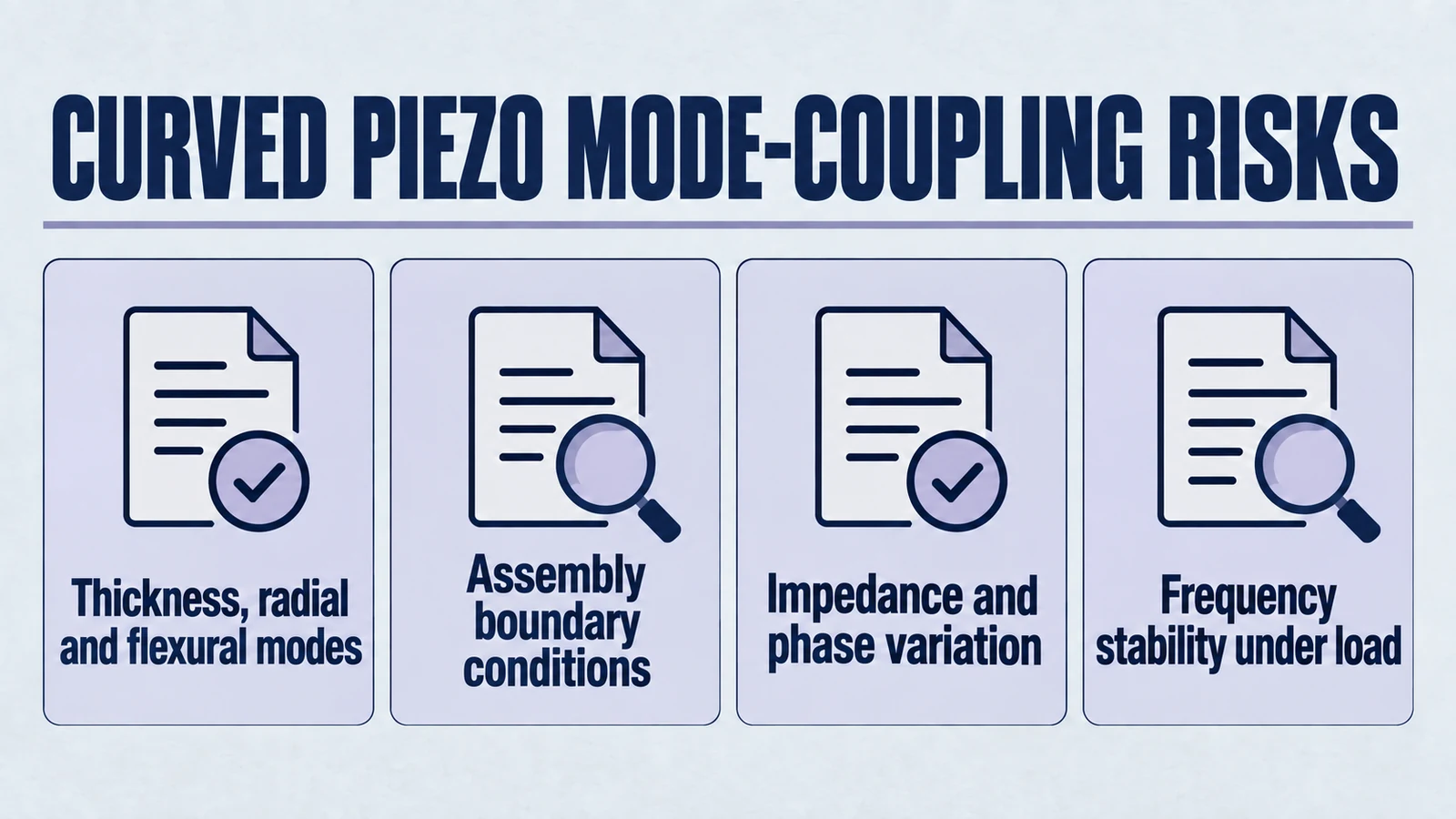
The reason is not that the ceramic has suddenly become mysterious. The reason is that curvature changes the mechanical rules of the structure. It changes how strain is distributed, how vibration patterns interact, how strongly neighboring modes can exchange energy, and how sensitive the element becomes to mounting, loading, adhesives, and temperature. What looked like a single operating resonance on paper can become a cluster of competing behaviors in real hardware.
This is where engineers get into trouble. A part may still measure "close enough" to its nominal resonance during incoming inspection. It may still produce ultrasound on the bench. It may even pass an early prototype milestone. But once the assembly is fully integrated, driven harder, thermally loaded, or exposed to variable acoustic conditions, mode coupling can turn frequency stability into a moving target. Related integration pitfalls are summarized in common OEM transducer integration mistakes.
Product path for this search intent
Match the article topic to the right YJ Piezo product page
Use this article when the choice is not just a shape, but a material tradeoff between sensitivity, loss, coupling, stability, and operating field. For "Mode Coupling Risks in Curved Piezoelectric Elements: Why Frequency Stability Is Harder...", the practical value is in turning the topic into a measurable selection or sourcing decision.
- PZT Material Hub
Material grades and application tradeoffs
- Piezoelectric Ceramics
Shapes and ceramic manufacturing options
- PZT Material Supplier Hub
Material control, grade selection, and sourcing support
This article is written as a decision-support guide, not a theory exercise. The goal is to help engineers understand why curved piezoelectric elements are more modal-sensitive than they first appear, what that means for tuning and repeatability, and when mode coupling becomes serious enough to change the selection decision.
The Real Issue: Resonance Is Rarely a Single Clean Event
When engineers talk about "the resonance frequency" of a piezo element, they are often referring to the thickness mode resonance, typically represented as . That is usually the most important one in ultrasonic design because it is strongly electromechanically active, relatively efficient, and often aligned with the intended operating mechanism of the transducer.
But no real piezoelectric ceramic vibrates in only one mode.
Even a simple flat disc supports multiple mechanical behaviors over frequency. The main families typically include:
- Thickness modes. Expansion and contraction through the thickness of the ceramic. These are often the intended working modes in ultrasonic power or sensing systems.
- Radial modes. In-plane expansion and contraction across the diameter or lateral dimensions of the part.
- Flexural modes. Bending or warping shapes that involve curvature of the ceramic body rather than mainly bulk compression through thickness.
In a flat element, those modal families may be separated enough, or weakly coupled enough, that engineers can still treat the main operating resonance as the dominant event. That is already an approximation. But it can be a useful one.
A curved element makes that approximation much less appropriate. Comparison background: focused vs flat piezoelectric ceramic behavior.
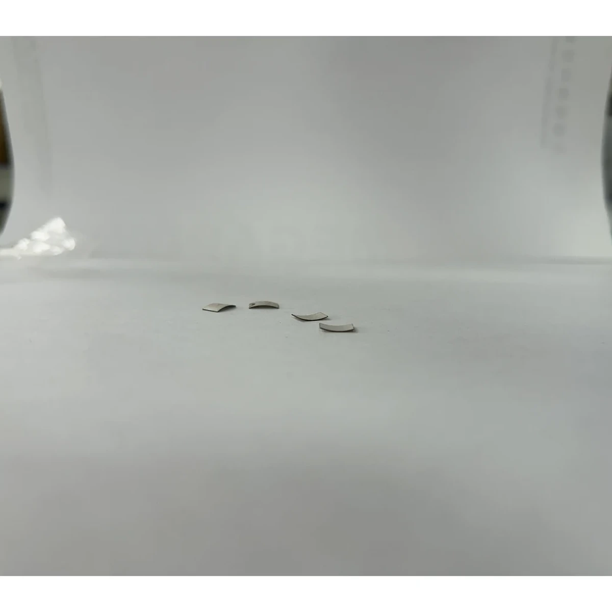
Curvature changes the structural behavior from something closer to a plate into something closer to a shell. Shell-like structures can support a richer set of vibration patterns. More importantly, those patterns do not remain neatly isolated. What would have been mostly thickness-driven motion in a flat geometry can gain bending character. Radial motion can become distorted by the curved shape. Flexural activity can move closer in frequency to the intended mode. The result is not just "more modes," but more opportunities for those modes to interact.
That interaction is what engineers usually experience as mode coupling.
In practical terms, mode coupling means that the energy you intended to place into one vibration pattern does not stay there cleanly. It can leak, redistribute, or switch dominance depending on operating conditions. The consequence is that frequency stability stops being a simple number and becomes a system behavior.
Why Curvature Increases Modal Complexity
To understand why curvature matters so much, it helps to think in terms of strain pathways rather than equations.
A flat ceramic driven in thickness mode is already not perfectly one-dimensional. But its dominant deformation can still be thought of as relatively straightforward. The electric field drives expansion and contraction through the thickness, while the rest of the structure responds within that constraint.
A curved ceramic is different. The geometry itself causes thickness motion, in-plane motion, and bending tendencies to interact more naturally. This happens for several reasons.
1) Curvature Mixes Deformation Types
In a curved shell, local thickness strain does not remain purely through-thickness in its mechanical consequences. Because the surface is curved, that motion can induce membrane-like strain and bending-like strain at the same time. The ceramic is not simply getting thicker and thinner. It is also redistributing stress over a curved surface.
That means a drive intended to excite one principal mode can feed nearby modes more easily than in a flatter, more separable structure.
2) Shell Structures Support Denser Modal Populations
Curved geometries tend to support more closely spaced vibration patterns than flat, simple plates of similar scale. This matters because modal spacing is a key practical variable. If neighboring modes are far apart, the working mode can remain dominant over a useful operating window. If neighboring modes are crowded, small perturbations can shift the energy balance.
Those perturbations do not have to be dramatic. A small adhesive thickness change. A slightly different backing stiffness. A slightly off-center bond line. A preload change. A few degrees of temperature rise. Any of these can be enough to shift which nearby mode looks dominant in the impedance response.
3) Symmetry Becomes Easier to Disturb
A theoretically perfect curved element might still show a manageable modal picture. Real assemblies rarely preserve perfect symmetry.
Once the ceramic is bonded into a housing, attached to matching layers, loaded by fluid or tissue, or constrained by edges that are not perfectly uniform, the ideal symmetry is broken. Broken symmetry can split or distort modal features. This is one reason a part that looks reasonable as a bare element may behave differently after integration.
4) Manufacturing Tolerances Act on More Than One Parameter at Once
A flat disc's dominant frequency is strongly influenced by thickness, but curved ceramics are affected by thickness plus radius of curvature, aperture, wall uniformity, edge trimming, and sometimes local forming nonuniformity. Each of those can influence not only the intended mode but also the position and strength of neighboring modes. Design variables are discussed in this radius-aperture-thickness guide and radius-of-curvature selection article.
This is why two curved elements that nominally share the same target frequency can still behave differently enough to complicate driver tuning.
Interaction Between Thickness, Radial, and Flexural Modes
The most useful mental model is to treat each mode family as a possible energy destination.
Electrical drive injects energy into the ceramic. The ceramic stores that energy mechanically. Some of it becomes useful acoustic output. Some of it becomes heat. Some of it remains trapped or redistributed among nearby structural modes.
If only one strong mode is participating, life is relatively simple. If multiple nearby modes are available and coupled, then the system becomes much less predictable.
Thickness Mode
Thickness mode is usually the intended operating mechanism in many ultrasonic piezo designs because it offers strong electromechanical coupling and a direct path from electrical excitation to acoustic generation. In a cleanly behaving part, this is the mode around which the driver, acoustic matching, and system target frequency are designed.
Radial Mode
Radial mode involves lateral expansion and contraction. In discs, rings, and caps, these modes can be significant depending on diameter, thickness ratio, electrode pattern, and boundary conditions. In some cases they are far enough away from the thickness resonance to be manageable. In other cases, especially in curved or large-aperture parts, they become close enough to distort the intended operating window.
Flexural Mode
Flexural behavior involves bending and shape deformation rather than primarily compressive thickness motion. Engineers often underestimate flexural participation because it may not dominate in a free, lightly supported measurement. But once a curved element is mounted, flexural participation can become much more relevant.
What Coupling Really Means Here
Mode coupling does not necessarily mean the ceramic is hopping chaotically between entirely separate resonances. Often it is subtler than that. It may mean:
- the impedance peak broadens or distorts
- the main resonance frequency shifts more under load than expected
- the phase response develops multiple sharp transitions
- one nearby mode steals more energy as the boundary condition changes
- the apparent best tuning point depends on drive level or fixture condition
This is why engineers sometimes say a part feels touchy, hard to tune, or not repeatable, even when no obvious severe defect exists. For a focused discussion dedicated to this topic, see mode coupling and geometry-driven risk in piezo ceramics.
Why Datasheet Resonance Values Can Be Misleading
Datasheets are useful. But for curved piezoelectric elements, they are often much less decision-complete than engineers assume.
Most datasheet resonance values are measured under controlled and simplified conditions. Typical conditions may include:
- free or lightly supported samples
- standard test fixtures
- air measurements or a specific water setup
- small-signal excitation
- limited sample counts
Those conditions are often suitable for material comparison, preliminary screening, or incoming reference checks. They are not always suitable for predicting how a focused ceramic will behave inside a real transducer assembly.
The Datasheet Gives a Measurement. Your System Creates a Different Problem.
A resonance frequency reported on a datasheet is a description of one test setup. It is not a promise that the same resonance will remain dominant once the part is bonded, backed, loaded, heated, and driven at application-relevant amplitude. To connect data-sheet assumptions with real driver behavior, review electrical driving challenges of focused piezo ceramics.
This matters especially in focused ceramics because the distance between nearby modes may already be small. A slight shift caused by mounting or loading may move the operating point toward a different modal balance.
Small-Signal Results Often Hide Large-Signal Behavior
Many resonance measurements are taken at low drive levels. That is reasonable for standardized characterization. But systems do not always operate at low signal.
At higher amplitude, several things can change:
- bond layers can contribute more nonlinear compliance
- local heating can shift material constants
- damping distribution can change
- fluid loading can become more influential
- parasitic modes can become easier to excite
So the resonance picture that looks neat at small signal may become less stable under actual operating power.
Single-Value Resonance Reporting Hides the Impedance Landscape
For curved parts, one resonance value is rarely enough. Engineers need to know the surrounding terrain, not just the headline number.
A single reported resonance frequency can conceal important realities such as:
- nearby secondary peaks
- asymmetry in the impedance curve
- broad shoulders that indicate mixed modal participation
- unstable phase behavior around the intended operating point
In other words, a datasheet value can be technically accurate and still operationally misleading.
The Bench-to-System Gap: Where Many Mistakes Happen
One of the most common engineering mistakes is assuming that if a curved ceramic behaves acceptably during early bench measurements, then the element itself is fundamentally suitable.
In reality, the bench test may be measuring a different problem than the final system will present.
Assembly Changes the Boundary Condition
As soon as the ceramic is bonded into a housing or transducer stack, its modal behavior changes. Adhesive thickness, adhesive modulus, backing damping, mounting stiffness, electrode routing, and contact uniformity all alter the structural boundary condition.
Curved elements are often more sensitive to these changes than flat ones because their modal population is already richer and more tightly spaced.
Acoustic Loading Changes the Apparent Stability
A transducer intended for use in air, water, tissue, gel-coupled contact, or process liquid does not see the same mechanical environment. The acoustic load shifts impedance behavior and affects how strongly different modes participate.
A part that looks stable in air may behave differently in water. A part that seems acceptable in a clean immersion tank may behave differently in a contact application with variable pressure and imperfect coupling.
Integrated Systems Add More Resonant Elements
In real products, the piezo ceramic is rarely alone. It is connected to backing, matching layers, front masses, housings, membranes, adhesives, and often a driver architecture with its own assumptions about resonance shape.
Mode coupling in the ceramic can interact with system resonances in the rest of the transducer assembly. Once that happens, the tuning challenge is no longer just about the ceramic. It becomes a stack-level integration problem. Architecture trade-offs between geometric focusing and other methods are discussed in ceramic geometry vs acoustic lenses.
That is why some focused ceramic selections look fine during component evaluation but become troublesome during system qualification.
What Mode Coupling Does to Tuning, Efficiency, and Consistency
Mode coupling is not only a physics curiosity. It has direct engineering consequences that affect driver design, acoustic performance, manufacturing yield, and field repeatability.
1) System Tuning Becomes Less Stable Than Expected
If the impedance response contains multiple nearby features, the question "where should we tune the driver?" becomes much harder than expected.
A fixed-frequency driver may land on different effective operating conditions from unit to unit. A frequency-tracking driver may chase the wrong local minimum or switch behavior as temperature changes. A manually tuned system may work well in one prototype and underperform in the next build.
This is not always because the electronics are poor. Sometimes the electronics are simply being asked to stabilize a structurally ambiguous resonant element.
2) Efficiency May Drop Without an Obvious Warning
A coupled parasitic mode can absorb energy without contributing meaningfully to the desired acoustic output. The system may still draw current and still seem active, but the useful acoustic conversion may degrade.
This can appear as:
- lower output at the intended focus
- broader or distorted beam profile
- reduced sensitivity in receive mode
- unexpected heating in adhesive or backing
- less stable process performance over time
From an engineering management perspective, this is dangerous because the system may pass a superficial functional check while quietly missing performance or reliability targets.
3) Repeatability Suffers Across Units and Conditions
Mode coupling is often condition-sensitive. If the dominant modal balance changes with temperature, loading, or assembly variation, then repeatability becomes difficult.
Typical symptoms include:
- prototype-to-prototype variation
- batch-to-batch tuning changes
- inconsistent impedance signatures in production screening
- output drift during warm-up
- performance changes under different coupling conditions
These are exactly the kinds of behaviors that consume engineering time because they do not always look like classic defects. Instead, they show up as ambiguous instability. You can compare this pattern with common failure modes in spherically curved ceramics.
4) Driver Safety Margins Can Erode
If the transducer's impedance behavior changes sharply with small frequency shifts, the driver may encounter conditions it was not designed to handle. Local minima may produce unexpectedly high current draw. Phase behavior may move outside the range assumed by the control loop. Protection thresholds may begin tripping intermittently.
What appears to be an electronics issue may in fact begin with modal uncertainty in the ceramic.
Why Frequency Stability in Focused Piezo Ceramics Is Harder Than It Sounds
Frequency stability is often discussed as if it were just a material property. In reality, for focused piezoelectric elements, it is a system-dependent outcome.
A part may be called frequency stable only after several questions are answered:
- stable under what drive level?
- stable under what temperature range?
- stable under what mounting stiffness?
- stable under what acoustic load?
- stable across how many production units?
- stable according to which metric: electrical resonance, acoustic output, or process result?
This is why engineers should be careful when using nominal frequency as a selection shortcut. A curved ceramic can meet a nominal target frequency in isolation and still fail the practical meaning of frequency stability in a real product.
That failure usually does not arrive as a single dramatic event. It arrives through accumulated evidence: difficult tuning, inconsistent batches, drifting performance, narrow process windows, and repeated rework during validation.
Scenarios Where Mode Coupling Becomes a Selection Deal-Breaker
Mode coupling does not automatically disqualify focused ceramics. Many high-value ultrasonic systems use curved elements successfully. But there are clear scenarios where mode coupling risk becomes serious enough that it should influence architecture selection.
Scenario A: Fixed-Frequency Systems With Narrow Operating Tolerance
If your system uses a fixed-frequency driver and depends on a narrow resonance window for efficient performance, then modal ambiguity is a major risk. A part whose effective operating point moves with temperature, load, or assembly details can create unacceptable spread.
In these applications, even modest resonance drift or peak reshaping can undermine acoustic output, power efficiency, or repeatability.
Scenario B: Applications With Highly Variable Loading
If the transducer sees variable tissue pressure, changing immersion depth, unstable coupling layers, cavitation-prone fluids, or other changing loads, then coupled modes can become much more active.
A design that behaves acceptably under a single laboratory load may become inconsistent under real-world operating variation.
Scenario C: Production Builds That Cannot Tolerate Unit-Level Tuning
If the business model or manufacturing process requires plug-and-play assembly with minimal calibration, then the modal behavior must be inherently robust. If each unit requires individual tuning to identify its best operating point, production cost and support burden rise quickly.
Focused ceramics are not impossible in this context. But the bar for tolerance control, process consistency, and incoming characterization becomes much higher.
Scenario D: Thermal Margin Is Already Limited
Parasitic modal participation often increases losses in places engineers do not want them, such as adhesives, backing layers, and constrained interfaces. If the design is already thermally tight, additional modal loss can accelerate aging, depoling, cracking, or bond degradation.
In these cases, mode coupling is not only a tuning issue. It becomes a reliability issue.
Scenario E: Beam Quality Matters as Much as Raw Output
Some applications care not only about whether ultrasound is generated, but about where the energy goes. If the system depends on focal sharpness, spatial repeatability, or clean acoustic distribution, then coupled modes can distort the field in ways that are unacceptable even when total power appears adequate.
This is particularly relevant in precision sensing, medical ultrasonics, and any design where beam consistency matters across units. Application constraints are discussed in focused piezo ceramics for medical ultrasound.
Practical Warning Signs During Evaluation
Engineers evaluating focused piezoelectric elements should not wait for severe failure to suspect mode coupling. There are earlier indicators.
Common warning signs include:
- multiple impedance peaks or shoulders near the intended operating band
- a phase curve with abrupt or unstable transitions
- resonance position changing noticeably with modest preload variation
- different samples showing different dominant peaks despite nominally identical dimensions
- frequency response that looks clean in free condition but messy after bonding
- output intensity changing more than expected with small temperature rise
- tuning that must be re-optimized after integrating backing or matching layers
None of these signs automatically means the part is unusable. But together they indicate that selection should not proceed on nominal frequency alone.
A More Useful Way to Evaluate Frequency-Sensitive Curved Ceramics
If your application depends on frequency stability, the evaluation plan should be built around modal robustness rather than only nominal resonance.
Step 1: Define the Stability Requirement in Operational Terms
Do not stop at a nominal target such as . Define what the system actually needs.
For example:
- acceptable impedance variation over temperature
- allowable acoustic output variation under load
- maximum acceptable drift during warm-up
- permitted unit-to-unit tuning spread
- driver appropriate operating range around resonance
Until that is defined, it is difficult to judge whether observed mode coupling is tolerable or disqualifying. Teams often track normalized drift such as across use conditions.
Step 2: Request Full Impedance and Phase Data, Not Only a Resonance Number
For curved ceramics, a single resonance value is not enough. Ask for:
- full impedance magnitude curves
- phase curves
- measurement conditions
- sample count and sample spread
- whether measurements were taken before or after any forming, bonding, or assembly step
This reveals whether the intended operating point is isolated and clean or surrounded by potentially troublesome neighbors.
Step 3: Evaluate in Assembly-Representative Conditions Early
Do not postpone realistic measurement until late-stage validation. The earlier you test under realistic boundary conditions, the faster you will learn whether the modal behavior is manageable.
Important variables to simulate include:
- actual backing concept
- representative adhesive type and thickness
- expected preload or clamping geometry
- intended acoustic medium
- expected temperature range
- realistic drive amplitude where practical
Measurement discipline from repeatable piezoelectric test and measurement workflows helps close this gap.
Step 4: Check Sensitivity, Not Just Nominal Performance
A prototype that performs well at one condition is not enough. Deliberately vary conditions to see how stable the response remains.
Useful perturbations include:
- small preload changes
- moderate temperature changes
- slight adhesive thickness variation
- sample-to-sample comparison
- multiple coupling media conditions if relevant
If the operating point shifts dramatically under small perturbations, the design may be too mode-sensitive for a production environment.
Step 5: Judge the Mitigation Burden Honestly
Mode coupling can often be managed. But management has a cost.
Possible mitigation paths include:
- broader driver bandwidth margins
- smarter tracking algorithms
- more damping in backing or structure
- tighter process control
- sample screening or acceptance windows
- unit-level tuning or calibration
The right question is not can this be made to work somehow. The right question is whether the required mitigation is compatible with cost, schedule, reliability, and the production model.
What to Ask Suppliers When Frequency Stability Matters
If you are sourcing focused piezoelectric elements for a frequency-sensitive application, the supplier conversation should go beyond target frequency.
Useful questions include:
- Can you provide impedance and phase curves for multiple production-representative samples?
- What fixture, preload, and medium were used in measurement?
- What is the tolerance range on thickness, curvature radius, aperture, and wall uniformity?
- Have you observed secondary resonances near the target frequency?
- How sensitive is the response to backing or adhesive differences?
- Do you have data showing frequency behavior over temperature or over repeated operation?
- Have similar parts been used in applications requiring narrowband or highly repeatable operation?
These questions do not by themselves confirm success. But they expose whether the supplier understands the practical modal risks rather than simply quoting a nominal resonance value.
When a Curved Element Is Still the Right Choice
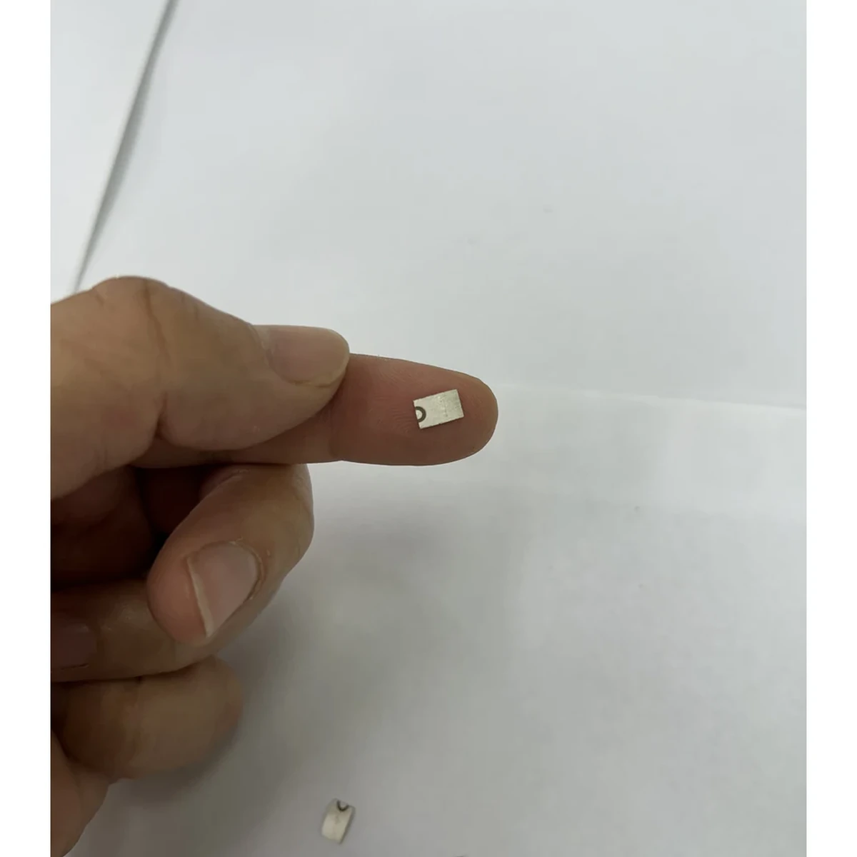
It is important not to overcorrect. Curved piezoelectric elements exist for good reasons. They can provide focused acoustic output, higher on-axis intensity, compact form factors, and architectural simplicity compared with some alternative focusing methods.
Mode coupling does not mean curvature is a bad design decision. It means curvature raises the burden of evaluation.
A focused ceramic can still be a very good selection when:
- the system can tolerate moderate frequency spread
- the driver has robust tuning or tracking capability
- the acoustic loading is relatively controlled
- the assembly process is consistent
- the application values focused output enough to justify added validation effort
The engineering mistake is not choosing curvature. The engineering mistake is choosing it while assuming the modal behavior will remain as simple as the datasheet headline suggests. For edge cases where this assumption fails, see when not to use focused piezoelectric ceramics.
Bottom Line: How Engineers Should Decide
Curvature increases the structural richness of a piezoelectric element. That richness can be useful acoustically, but it also makes the resonance behavior more conditional, more sensitive, and more dependent on real assembly and operating conditions.
Mode coupling is the practical expression of that complexity. It shows up when thickness, radial, and flexural behaviors interact closely enough that energy no longer stays cleanly in the intended working mode. When that happens, engineers see the consequences as unstable tuning, unpredictable efficiency, reduced repeatability, and hard-to-explain performance drift.
That is why datasheet resonance values, by themselves, are not enough for focused piezo ceramic selection.
If your application demands tight frequency stability, narrowband operation, minimal calibration, high repeatability, or limited thermal risk, then curved piezoelectric elements should be judged on modal robustness, not merely on nominal frequency. In some projects, that leads to a successful focused design with careful validation. In others, it becomes the reason to reconsider the architecture before too much time is invested.
The honest engineering decision is not whether mode coupling exists. It almost always does to some degree. The real decision is whether your system can tolerate it, control it, or justify the cost of engineering around it.
About Yujie: Supporting Selection Beyond Nominal Resonance
At Yujie Technology, we work with OEM engineers evaluating piezoelectric ceramics and ultrasonic transducer elements for frequency-sensitive applications. For focused or curved elements, good selection decisions usually depend on more than a target frequency. They depend on understanding impedance behavior, tolerance sensitivity, boundary conditions, and integration risk. If your project has tight requirements around resonance stability, consistency, or driver matching, it is worth discussing those conditions early rather than relying only on nominal datasheet values.
For component paths and early engineering alignment, you can review spherical-cap piezo ceramics for RFQ review, the broader piezoelectric ceramics catalog, or contact engineering directly via the contact page.
Related Technical Reading
Focused geometry and mode behavior
- Spherically curved piezoelectric ceramics: practical introduction
- Key design parameters: radius, aperture, and thickness
- How to choose radius of curvature in focused ceramics
- Focused vs flat piezoelectric ceramics
- Mode coupling and geometry-driven risk
Driver stability and system validation
- Electrical driving challenges of focused piezo ceramics
- Selecting piezo ceramics for continuous-duty operation
- How to test and measure piezoelectric materials
- Common integration mistakes in OEM ultrasonic systems
Reliability and selection strategy
Engineering decision notes
PZT material and ceramic selection
Use this article when the choice is not just a shape, but a material tradeoff between sensitivity, loss, coupling, stability, and operating field. For "Mode Coupling Risks in Curved Piezoelectric Elements: Why Frequency Stability Is Harder...", the practical value is in turning the topic into a measurable selection or sourcing decision.
YJ Piezo coordinates PZT ceramic projects with manufacturing support, so material formulation, sintering, polarization, electrode process, and outgoing inspection can be reviewed against the final application.
Selection checks
- Separate sensing needs from high-power actuation needs before comparing d33 or coupling values.
- Check dielectric loss, Qm, Curie temperature, aging behavior, and operating field against the real duty cycle.
- Confirm whether the application needs standard PZT grades or a custom formulation and geometry.
Failure risks
- Choosing only the highest d33 can create heat, drift, or depolarization risk in power ultrasonics.
- A ceramic that performs well in free measurement can fail once bonded, clamped, or loaded.
- Material substitutions without batch testing can change capacitance, resonance, and system tuning.
RFQ details
- Is the part used for sensing, actuation, atomization, cleaning, welding, or measurement?
- What field strength, temperature, duty cycle, and mechanical load will the ceramic see?
- Which values must be controlled: d33, capacitance, resonance, impedance, Qm, or dimensional tolerance?
Relevant YJ Piezo pages
- PZT Material Hub
Material grades and application tradeoffs
- Piezoelectric Ceramics
Shapes and ceramic manufacturing options
- PZT Material Supplier Hub
Material control, grade selection, and sourcing support
Application FAQ
- Is the highest d33 always the best PZT choice?
- No. High d33 can be useful for sensitivity, but high-power ultrasonic systems often need lower loss, higher Qm, better thermal stability, and safer operation under field and stress.
- What makes PZT material selection different from catalog buying?
- The right PZT choice depends on geometry, load, drive field, duty cycle, temperature, and inspection targets. A catalog value is only useful when it is tied to the final assembly conditions.