
Common Mistakes When Integrating Ultrasonic Transducers into OEM Systems
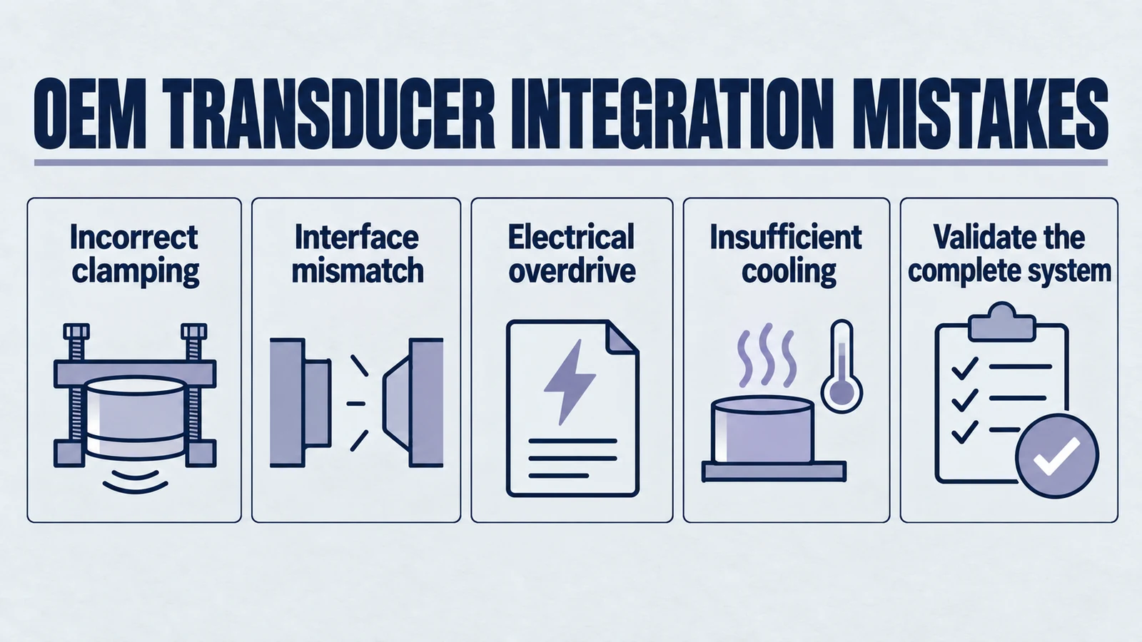
By Yujie Piezo Engineering Team
Audience: OEM engineers integrating ultrasonic transducers into custom equipment
Scope: recurring integration errors that cause weak output, instability, overheating, or early-life failures
Ultrasonic transducers rarely fail because the piezo stack “was bad.” Most failures show up after integration, when a transducer that behaved perfectly on a bench becomes unstable inside a real machine: mounting changes boundary conditions, enclosure panels become unintended radiators, drive electronics assume a fixed load, cabling adds reactive load, and heat has nowhere to go.
If you have ever said “it worked fine in our lab” and then watched it drift, squeal, overheat, or quietly lose output in the field... this is that story. Integration turns a catalog component into a coupled electromechanical system. Once installed, the transducer is no longer “the same part.” It is your resonator.
This article is not a list of generic best-practice slogans. It is a catalog of integration mistakes that keep repeating in OEM programs, why they happen, how they present in hardware and field returns, and the minimum checks that catch them early enough to matter.
Product path for this search intent
Match the article topic to the right YJ Piezo product page
Use this article when the risk is supplier selection, engineering support, validation evidence, integration reliability, and whether the manufacturer can scale from sample to production. For "Common Mistakes When Integrating Ultrasonic Transducers into OEM Systems", the practical value is in turning the topic into a measurable selection or sourcing decision.
- Ultrasonic Transducer Supplier Hub
OEM sourcing and engineering collaboration
- PZT Material Supplier Hub
Material control and grade selection
- Piezoelectric Ceramics
Ceramic manufacturing and custom shapes
1. Mistake: Treating the transducer like a rigid bolt-on part
What goes wrong
An ultrasonic transducer is not a rigid actuator you can clamp however you like. It is a resonant mechanical system. The mounting interface is part of the resonator.
When you change how the transducer is constrained, you change:
- Resonant frequency and impedance.
- Mode shape (where strain concentrates).
- Mechanical (how sharply it resonates).
- How energy leaks into the surrounding structure.
A mount that seems “stronger” often increases damping or shifts the resonance into a region the driver cannot track. Worse, the mount can introduce bending modes that were never present in the free-state test.
One quiet trap is “partial constraint.” A clamp that is stiff in one direction and compliant in another can produce mixed modes. It is still “tight” by feel... it is unstable by physics.
How it shows up
- Resonant frequency shifts after installation (sometimes by hundreds of Hz or more depending on size and frequency).
- “Works on bench, weak in machine.”
- Higher drive current at the same output, or reduced output at the same current.
- Strong unit-to-unit variation driven by small assembly differences.
- Random overheating, cracked ceramics, or loosened preload after a short time.
The minimum check
Measure impedance and resonance in the final mount, not just in isolation. If your electrical drive expects a resonance at 20.0 kHz and the installed system is now 19.6 kHz with a different phase curve, you did not “get unlucky.” You changed the load.
If you can only do one diagnostic early... do “free vs installed” impedance sweeps and archive the curves. When you later get field units back, those curves are your fingerprints.
2. Mistake: Ignoring mechanical impedance mismatch at the interface
What goes wrong
Energy transfer in ultrasonics is impedance matching, but many teams only think about impedance electrically.
Mechanical impedance at the interface matters just as much:
- If the mount is too compliant, the transducer spends energy flexing the mount.
- If the mount is too massive or too stiff in the wrong direction, you reflect energy back into the stack.
- If the interface is imperfect (gaps, uneven contact, soft pads), you create frictional heating and micro-slip.
A common culprit is a mounting plate or bracket that looks “solid” but has low stiffness in the vibration direction due to geometry. Another is a surface that is flat by machining standards but not flat enough for ultrasonic contact pressures. A third is “mystery compliance”... paint, anodize thickness variation, or a thin polymer layer that was added for corrosion resistance and accidentally became a damper.
How it shows up
- Strong output at low power, then collapse at higher power.
- Rising temperature localized at the interface region (not in the driver).
- Audible squeal or buzzing. That is structure-borne vibration turning into airborne sound.
- Fast loosening of fasteners due to micro-slip.
- Powdering or fretting marks at contact surfaces.
The minimum check
- Verify contact flatness and perpendicularity where it matters.
- Verify preload is maintained under operating temperature and vibration.
- Compare “installed vs free” impedance sweeps. A large change in peak sharpness and phase slope is a red flag.
If you see fretting... stop thinking “loctite.” Start thinking “slip.” A threaded lock can hide the symptom while the interface continues to heat and drift.
3. Mistake: Overconstraining the node. Clamping where the transducer wants to move
What goes wrong
Resonant transducers have nodes and antinodes. If you clamp near an antinode, you add loss and stress. If you clamp at the node but your node location moves under load or temperature, you still get loss and stress.
OEM designs often clamp wherever packaging is convenient. Unfortunately, packaging convenience has no respect for mode shapes.
Two subtler versions of this mistake show up frequently:
- The node is correct for the transducer alone... but the node shifts when the horn, booster, or medium load is attached.
- The clamp is “at the node” radially... but introduces bending constraint that excites a different mode family.
How it shows up
- High drive current with low acoustic output.
- Rapid heating even at moderate power.
- Cracks near ceramic edges or at adhesive boundaries.
- Sensitivity to tiny assembly variations (one unit passes, the next fails).
- High audible noise compared with the same transducer outside the machine.
The minimum check
If the manufacturer provides node location guidance... treat it as a constraint, not a suggestion.
If no guidance exists, measure mode shape in the integrated assembly using a basic approach (accelerometers, laser vibrometry if available, or even comparative output mapping). The goal is not perfection. The goal is to confirm you are not clamping the moving region.
A practical rule: if your clamp design would also work as a “stiffener” for the vibrating part... it is probably clamping the wrong place.
4. Mistake: “More power fixes it.” Overdriving into thermal runaway
What goes wrong
When output is low after integration, teams often increase drive voltage or duty cycle. That sometimes restores output temporarily, but it can drive the system into a thermal runaway loop:
- Loss mechanisms (dielectric loss, mechanical loss, interface friction) convert a fraction of input power into heat.
- Many losses increase with temperature.
- As temperature rises, resonance shifts and the load becomes harder to drive efficiently.
- The driver delivers more current to maintain amplitude, creating more heat.
Detuning changes the complex impedance and the driver’s operating point. Current may increase or decrease depending on the drive strategy, matching and maintained amplitude; at fixed voltage, moving away from a series-resonance impedance minimum may reduce current. Diagnose voltage, current, phase, output and temperature together.
Another trap: what looks like “we need more voltage” is often “we lost coupling”... poor mounting, poor load contact, or a detuned resonance makes the system inefficient. More power mostly turns into heat.
How it shows up
- Temperature rises nonlinearly with drive. It looks “fine” then suddenly climbs.
- Output becomes unstable... amplitude drifts or oscillates.
- Early-life ceramic cracking, electrode degradation, or depoling.
- Adhesive softening, preload loss, and stack rattle.
- Driver component stress. MOSFETs and magnetics running hot because reactive power increased.
The minimum check
- Track temperature at the transducer body and at the mount interface during a realistic duty cycle.
- Watch for current vs frequency behavior. A rising current at fixed amplitude is often the earliest warning.
- Do not accept “it survived a 5-minute bench run” as proof. Many failures are cumulative and appear after heat soak.
If you are forced to increase power during debugging... do it with a hard stop condition (temperature, current, or phase margin). Don’t let “temporary success” become the new operating point.
5. Mistake: Assuming air around the transducer is “cooling”
What goes wrong
In many OEM enclosures, airflow is minimal and radiative cooling is limited. A transducer can be effectively insulated by:
- Plastic housings.
- Foams and seals added for acoustics or ingress protection.
- Proximity to heat sources (motors, power supplies, heaters).
- Mounting to a thermally poor structure.
A design that is thermally stable on an open bench can be marginal in a sealed machine.
Thermal failures can look like electrical failures because detuning is temperature-driven. The driver sees a changing load... the control loop hunts... current spikes appear “random.”
How it shows up
- No issues in early testing. Failures after longer runtime.
- Strong dependence on ambient temperature.
- Units pass in winter and fail in summer.
- Drift in frequency or output after warm-up.
- Output that degrades over time, then “recovers” after a cool-down.
The minimum check
Treat thermal design as a first-class integration item. If you cannot move heat out, reduce losses or reduce duty. If you cannot reduce duty, redesign the thermal path.
Minimum reality test: run to thermal steady-state in the actual enclosure at the worst ambient you expect. If you never reach steady-state in testing... you do not know where the system wants to settle.
6. Mistake: Inadequate acoustic isolation. Letting the enclosure become a second transducer
What goes wrong
The acoustic energy you intend to send into a horn, tank, or medium will also propagate into any mechanically connected structure. If the enclosure has panels, cavities, or brackets that can resonate, you have built a second radiating system. It steals energy and creates unpredictable coupling.
This is often mistaken for “electrical noise” because it presents as unstable amplitude, sensor interference, or spurious vibrations.
A particularly annoying failure mode is “path-dependent behavior”... the machine behaves differently depending on what is bolted nearby, what is touching a panel, or even how a cable harness is zip-tied.
How it shows up
- Audible noise and rattling from modulation, subharmonics or lower structural modes. Harmonics of an ultrasonic fundamental are higher-frequency, not an explanation of audible sound by themselves.
- Interference with nearby sensors (ultrasonic, load cells, cameras) due to vibration.
- Fatigue cracks in sheet metal, mounts, or welds near the transducer.
- Variation across units because enclosure tolerances shift resonances.
- Operator complaints... “it screams,” “it buzzes,” “it feels like it’s shaking the whole machine.”
The minimum check
- Identify the mechanical path from transducer to chassis. If there is a hard path, assume energy will enter the chassis.
- Compare vibration signatures of the chassis with transducer on and off. If large chassis acceleration exists near operating frequency, isolation is not optional.
If your chassis has a thin panel near the operating frequency... treat it like a diaphragm speaker, because that is what it will become.
7. Mistake: Treating the driver as a fixed-frequency power supply
What goes wrong
Ultrasonic loads are not fixed. Resonance shifts with:
- Temperature.
- Preload changes.
- Medium contact conditions (liquid level, viscosity, pressure).
- Aging, wear, and mounting relaxation.
If the driver assumes a fixed operating frequency, it will spend time off-resonance, pulling high current for low output. If it assumes the load looks like a resistor, it will misinterpret reactive power.
This mistake becomes acute when the application itself changes load rapidly... for example, intermittent contact, changing liquid levels, or variable pressure conditions.
How it shows up
- High current, low output, rapid heating.
- Inconsistent output across operating conditions.
- Overcurrent trips that appear “random.”
- Repeat failures of MOSFETs or transformers due to reactive stress.
- A system that only behaves when manually retuned... then drifts again.
The minimum check
Your driver needs a way to deal with a moving resonance. That can mean frequency tracking, phase-locked control, or at minimum a detection method that stops the system from driving into a detuned condition.
A practical integration test is to run impedance sweeps across temperature and under expected loading. If the resonance moves more than your control bandwidth can handle, the driver strategy is not aligned with the physics.
If you must operate at fixed frequency for system reasons... then the mechanical design must constrain drift. Don’t ask the electronics to do magic.
8. Mistake: Forgetting that cabling and layout become part of the resonant system
What goes wrong
At ultrasonic drive frequencies and power levels, wiring choices matter:
- Cable capacitance adds reactive load.
- Long leads increase EMI and voltage overshoot.
- Poor grounding creates unexpected current loops.
Some teams copy a bench setup... then relocate the driver farther away in the final machine. The transducer load seen by the driver is now different.
A second trap is routing... cables routed near switching supplies or motor leads can inject noise that the control loop misreads as resonance movement.
How it shows up
- Driver instability only when installed in the full machine.
- Excessive EMI, false triggering of sensors, communications errors.
- Higher-than-expected transducer voltage peaks.
- Premature driver component failures.
- Units that pass in one cabinet layout and fail in another.
The minimum check
Validate the system with production-intent cable lengths, routing, shielding, and grounding. If you only validate in a lab harness and then change the harness... you did not validate the final system.
If your control strategy uses phase sensing... do not assume phase measurement is immune to layout. It is often the first thing that becomes unreliable.
9. Mistake: Making electrical drive assumptions from a “similar-looking” transducer
What goes wrong
Two transducers with similar size and nominal frequency can behave very differently:
- Different piezo material (loss tangent, , coupling).
- Different stack geometry.
- Different preload method.
- Different horn or mass loading.
Assuming the same drive voltage, same frequency, same duty cycle, or same matching network is a common integration shortcut. It is also a common root cause of overheating and inconsistent performance.
This is where OEM programs get burned during supplier changes. The mechanical envelope is identical... the electromechanical behavior is not.
How it shows up
- Prototype works with one supplier... fails with another.
- Production units vary more than expected.
- Driver tuning becomes a trial-and-error loop late in the program.
- A “secret” rework process appears on the line... because the design cannot tolerate normal variation.
The minimum check
Demand the characterization that matters for integration: impedance curves, resonance/anti-resonance, recommended preload, expected frequency shift with temperature, and loss behavior under duty.
If you cannot obtain this data, plan to measure it yourself early. The cost of a measurement setup is low compared to a field failure campaign.
As an OEM... your job is not to guess which transducer is “close enough.” Your job is to control the interfaces and validate the drift space.
10. Mistake: Skipping failure-mode testing. Only testing “does it work today?”
What goes wrong
Many integration plans validate immediate function: output, frequency, current. They do not validate the failure modes that actually occur:
- Heat soak at maximum duty.
- Start-stop cycles (thermal cycling + preload cycling).
- Off-nominal loading (empty tank, wrong medium, partial contact).
- Enclosure resonance changes across temperature.
A system can look stable for minutes and still be destined to fail in weeks.
The testing failure is often philosophical: teams avoid “ugly” conditions because they are not the nominal spec. Customers then operate in those ugly conditions anyway.
How it shows up
- Failures cluster after a certain number of hours.
- Failures correlate with customer usage patterns rather than assembly defects.
- “It passed our test, but customers break it.”
- Postmortems that blame “abuse” while the design had no guardrails.
The minimum check
Define at least one test that intentionally stresses the integration weak points: detuning, thermal saturation, isolation path excitation, and electrical reactive stress. Not as a perfection exercise. As a way to discover what breaks before the customer does.
If your system has a driver that can log frequency, phase, current, and temperature... use it. A handful of logged plots is often worth more than weeks of debating root cause.
A Cautionary Integration Checklist (Mistake-Driven)
Use this as a quick audit when an ultrasonic transducer “mysteriously” underperforms or fails early:
- Installed impedance sweep matches bench behavior... if not, the mount is changing the system.
- Mount interface has verified contact quality and stable preload across temperature.
- Clamp location avoids high-motion regions under real load and temperature... not just on paper.
- Temperature rise is measured at realistic duty cycles... not inferred.
- Driver strategy tolerates resonance drift... it does not assume fixed frequency.
- Enclosure vibration is measured... the chassis is not acting like a radiator.
- Cabling and grounding are validated in production-intent configuration.
- Drive settings are based on characterization... not similarity assumptions.
- Heat-soak, cycling, and off-nominal load tests exist... function-only testing is not enough.
Closing perspective
The fastest way to waste time in ultrasonics is to treat integration as “installation.” The fastest way to ship a reliable system is to treat the installed transducer as a coupled electromechanical resonator whose boundary conditions you are responsible for.
If you want one practical rule of thumb: the moment the transducer enters your machine... you own its resonance.
And if you want one uncomfortable truth: most integration failures are predictable. They just weren’t measured in the final configuration until it was too late.
Related Technical Resources
Use these internal references to compare geometry, material selection, reliability testing, and sourcing decisions.
- Mode Coupling Risk in Piezo Ceramic Geometry
- Selecting Piezo Ceramics for Continuous Duty Applications
- Troubleshooting Piezo Devices: Common Failures and Prevention
- Piezoelectric Ceramics Geometry and Shape Guide
- Understanding Ultrasonic Transducers: Types and Uses
- How to Test and Measure Piezoelectric Materials
- Understanding Piezoelectric Constants d33, k, and Qm
- Ensuring Quality of Piezoelectric Components
Engineering decision notes
OEM integration and supplier qualification
Use this article when the risk is supplier selection, engineering support, validation evidence, integration reliability, and whether the manufacturer can scale from sample to production. For "Common Mistakes When Integrating Ultrasonic Transducers into OEM Systems", the practical value is in turning the topic into a measurable selection or sourcing decision.
YJ Piezo combines direct project coordination with ceramic manufacturing support, so procurement and engineering teams can evaluate material control, application review, sample validation, and production consistency together.
Selection checks
- Ask whether the supplier controls ceramic manufacturing or only assembles purchased elements.
- Review sample policy, inspection records, engineering response quality, and production lead-time stability.
- Compare suppliers and integration paths by validation evidence, not only by unit price and datasheet similarity.
Failure risks
- A low-price sample can pass early tests but fail when batch variation, thermal load, or assembly stress appears.
- A supplier without material control may not explain why impedance, capacitance, or resonance drift occurs.
- Weak RFQ information leads to quotes that are fast but not technically comparable.
RFQ details
- What application, operating environment, and failure cost should the supplier design around?
- Which sample tests and outgoing records are required before pilot production?
- What customization, MOQ, tooling, and delivery constraints must be known before quotation?
Relevant YJ Piezo pages
- Ultrasonic Transducer Supplier Hub
OEM sourcing and engineering collaboration
- PZT Material Supplier Hub
Material control and grade selection
- Piezoelectric Ceramics
Ceramic manufacturing and custom shapes
Application FAQ
- How should an OEM compare piezoelectric suppliers?
- Compare material control, engineering support, test evidence, customization ability, sample policy, and batch consistency. Unit price matters, but only after the technical risk is understood.
- What makes an RFQ technically useful?
- A useful RFQ includes application, dimensions, target frequency, electrical limits, duty cycle, operating medium, environment, expected quantity, required reports, and current failure or replacement context.