
OEM Piezoelectric Transducer Manufacturing Workflow: From Prototype to Production
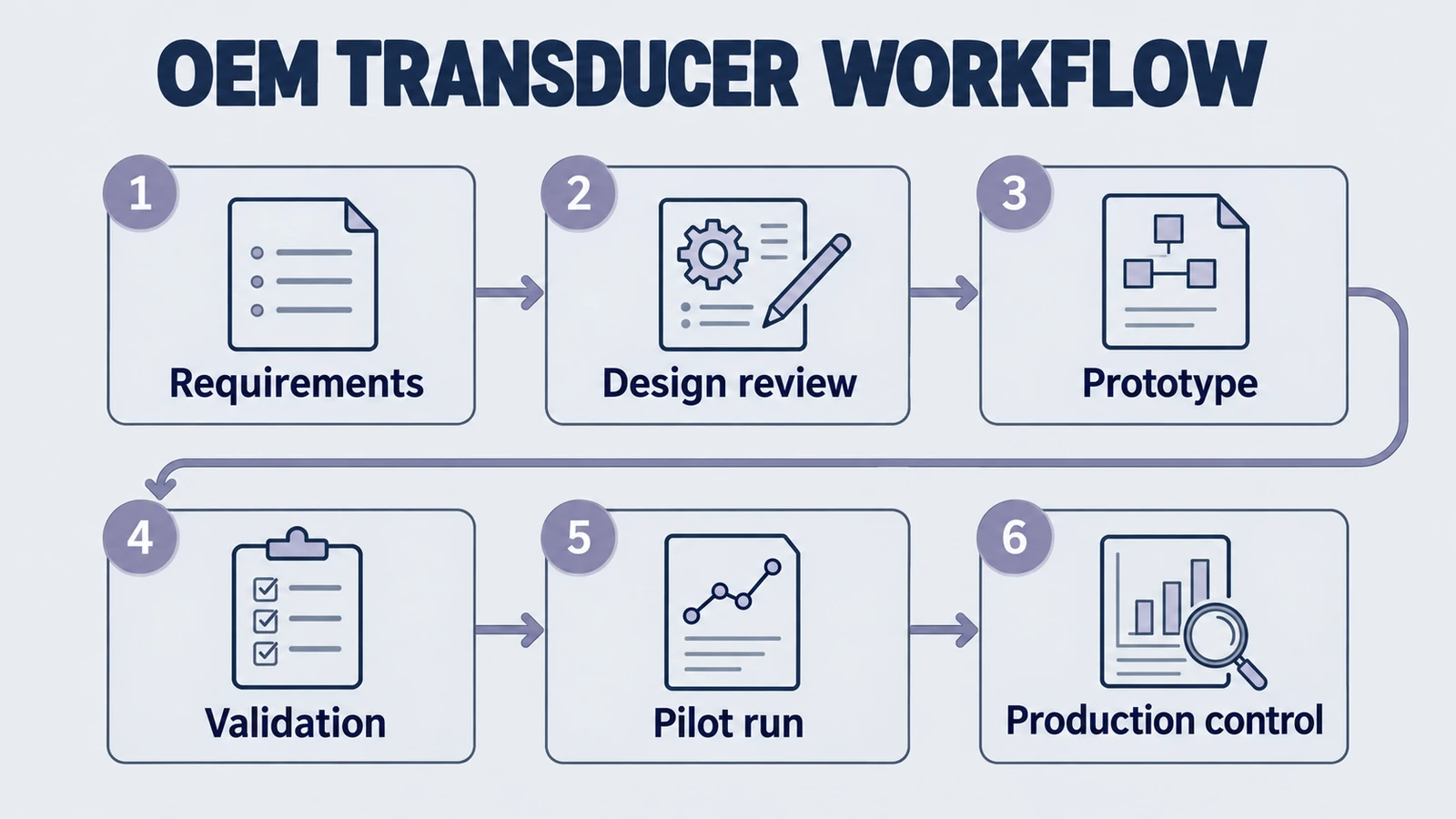
Most OEM teams do not fail because they picked the wrong buzzword. They fail because the development workflow between concept, sample, validation, and scale-up was never made explicit. A piezoelectric transducer program can look healthy at sample stage, then fall apart when the first production lot arrives with drift in resonance, unstable bonding, or inconsistent acoustic output. That is why this article stays focused on the manufacturing workflow itself.
If your main question is whether a factory has the technical depth to control PZT materials, FEA, pre-stress engineering, stabilization, and validation discipline, use our technical manufacturer benchmark. If the real issue is partner fit during co-development, NPI, and engineering communication, use our innovation partner guide. This page is narrower on purpose: it explains how an OEM transducer program should move from requirement definition to stable production.
1. Start by locking the program inputs, not by asking for a random sample
A productive OEM workflow begins before the first drawing or prototype PO. The transducer manufacturer needs enough context to understand what the acoustic system is trying to do, how it will be mounted, and what failure modes matter most. Without that context, the factory may still ship a sample, but the sample is unlikely to represent the production path you actually need.
Product path for this search intent
Match the article topic to the right YJ Piezo product page
Use this article when the risk is supplier selection, engineering support, validation evidence, integration reliability, and whether the manufacturer can scale from sample to production. For "OEM Piezoelectric Transducer Manufacturing Workflow: From Prototype to Production", the practical value is in turning the topic into a measurable selection or sourcing decision.
- Ultrasonic Transducer Manufacturer & Supplier Hub
Published product families, custom OEM review, RFQ inputs, and project-specific validation planning
- PZT Material Supplier Hub
Material control and grade selection
- Piezoelectric Ceramics
Ceramic manufacturing and custom shapes
At minimum, the OEM side should define:
- Application function: sensing, cleaning, welding, underwater acoustics, medical, or actuation.
- Operating environment: duty cycle, temperature range, media exposure, pressure, humidity, and shock or vibration conditions.
- Mechanical envelope: allowable diameter, thickness, housing constraints, preload method, and cable or connector strategy.
- Electrical target: resonance band, impedance window, capacitance target, drive voltage, and matching requirements.
- Business boundary: MOQ, target lead time, validation timeline, and any regulatory or documentation requirements.
That input package is what turns a supplier into a real development participant. If the manufacturer has to infer everything from one old sample and a nominal frequency label, your program is already handing control to guesswork.
2. DFM decisions should happen before the prototype is frozen
Once the application envelope is clear, the next phase is not “build whatever resembles the old part.” It is design-for-manufacturability. This is where the OEM team and the factory decide which parts of performance must be protected at all costs and which trade-offs are acceptable for yield, cost, and lead time.
Typical DFM decisions include:
- Material family: hard PZT for high-power continuous duty, softer formulations for sensitivity, displacement, or receive performance.
- Geometry family: discs, rings, tubes, rectangular plates, or curved parts depending on power handling, packaging, and beam behavior. If the geometry is still open, use our geometry selection guide before moving deeper.
- Electrode and metallization choices: silver, nickel, gold, segmentation logic, solderability, and long-term corrosion behavior.
- Acoustic stack decisions: backing, matching layers, horn or mass design, bond-line thickness, and mounting method.
- Tolerance strategy: which dimensions and electrical parameters must be tightly controlled, and which can sit in a broader commercial window.
This phase matters because prototypes that ignore DFM often create a false sense of progress. The unit works on a bench fixture, but the build relies on hand tuning, selective assembly, or a material lot the supplier cannot reproduce consistently. A healthy OEM workflow forces those questions forward before validation starts.
3. A prototype plan should define learning goals, not just sample quantity
Prototype stage is not simply the act of receiving ten parts and hoping one performs well. Each round should have a defined learning goal. Otherwise the project burns time collecting measurements that do not move the program toward production readiness.
A practical prototype sequence usually looks like this:
- Feasibility samples: confirm the basic architecture can hit the rough acoustic and electrical targets.
- Engineering samples: tighten material choice, geometry, bonding stack, and interface details.
- Pilot-intent samples: built using tooling, process windows, and inspection logic closer to production reality.
Each round should answer explicit questions. Does the transducer meet resonance and impedance targets? Is the thermal rise acceptable at duty cycle? Does the bonding process create stable acoustic output? Is the tolerance stack robust, or only the “best” sample performs? When a sample round does not answer a question, it becomes noise instead of progress.
For teams screening technical manufacturer capability during these prototype rounds, our manufacturer quality benchmark is the right companion page. It helps separate process-capable factories from those that merely ship plausible-looking parts.
4. Validation must measure the full stack, not only the ceramic element
One of the most common OEM mistakes is validating only the ceramic or only the no-load electrical response. That may be useful for material screening, but it does not validate the product you are actually going to sell. The production transducer is a system: ceramic, metal parts, adhesive, preload, cable, matching layers, encapsulation, and test conditions all interact.
A robust validation plan usually covers:
- Electrical validation: resonance, anti-resonance, impedance, capacitance, phase behavior, and drift after aging.
- Acoustic validation: output level, beam pattern, sensitivity, cavitation performance, or receive response depending on application.
- Mechanical validation: torque or preload sensitivity, interface flatness, assembly repeatability, and vibration survivability.
- Environmental validation: thermal cycling, humidity exposure, immersion, chemical resistance, or pressure testing where relevant.
- Lifetime validation: endurance under realistic duty cycle, not just short bursts on a lab power setting.
The real purpose of validation is to prove that your chosen architecture can survive normal variation. If the transducer passes only when assembled by the best technician, with the best adhesive batch, and with a narrow tuning adjustment, the design is not ready for pilot run.
5. Pilot run is where the workflow either matures or collapses
Pilot production is not a ceremonial step. It is where the manufacturer proves that the chosen process can survive scheduling pressure, lot variation, and ordinary factory execution. Many OEM teams skip this learning and move from engineering samples directly to volume. That usually postpones the real problems until the first commercial shipment.
A disciplined pilot run should verify:
- Traveler and documentation control: clear work instructions, revision locking, and traceability by lot or batch.
- Incoming material control: ceramic lot verification, metal part tolerances, adhesive shelf-life, and cable consistency.
- In-process checkpoints: poling verification, bond cure controls, torque or preload recording, and assembly screening.
- Outgoing data package: electrical test records, acceptance windows, lot summaries, and nonconformance handling.
- Capacity realism: lead time and yield under pilot conditions, not only in a hand-built engineering cell.
The goal is to learn whether the factory has a repeatable system. A good pilot run gives the OEM a stable release path into production. A bad pilot run is still useful because it reveals exactly where change control, inspection logic, or process capability are not ready yet.
6. Scale-up depends on change control, not optimism
Once the transducer moves beyond pilot quantities, the biggest risks are no longer conceptual. They become operational: silent raw-material substitution, tooling wear, adhesive variation, over-compressed lead times, and undocumented changes made to “help shipment.” Scale-up needs a disciplined agreement on what can change, who signs off, and what revalidation is required.
Before approving mass production, the OEM team should align with the manufacturer on:
- Change notification rules: material source changes, process window changes, tooling replacements, and inspection method changes.
- Lot release criteria: what data must accompany each shipment, and what happens when a lot drifts near a limit.
- Escalation path: who handles field failures, line stops, or abnormal returns, and how quickly.
- Capacity expansion logic: how the process will be duplicated or scaled without resetting the validation burden.
- Feedback loop: how field data and production rejects are fed back into DFM and reliability improvement.
This is also where partner behavior starts to matter more than brochure language. If your real concern is whether the manufacturer can stay aligned with your engineers during this stage, go back to our innovation partner guide. That page stays focused on collaboration model and program risk, while this page stays focused on the workflow mechanics.
7. A simple question set for OEM teams
When reviewing a transducer manufacturer, these questions help expose workflow maturity fast:
- What are the official gates between feasibility sample, engineering sample, pilot run, and mass production?
- Which parameters are measured on every unit, and which are measured by sampling plan only?
- How is torque, preload, or bond cure controlled during assembly?
- What triggers revalidation when material, tooling, or process changes occur?
- Can the supplier show lot-level records from a previous production program?
- How does the factory handle a pilot run that misses yield or acoustic targets?
Factories with real workflow discipline answer these questions concretely. Factories that operate on heroics usually answer with general claims about experience and quality.
Conclusion: Treat manufacturing workflow as part of the product
An OEM piezoelectric transducer is not only a ceramic element plus a drawing. It is the output of a workflow: requirement definition, DFM, prototype learning, validation, pilot execution, and controlled scale-up. If that workflow is vague, the product stays fragile even when the first samples look promising.
Use this page when your team needs to structure the path from concept to production. Use our technical manufacturer benchmark when you need to audit process depth, and our innovation partner guide when you need to judge collaboration fit. Together, those three pages answer different questions inside the same OEM decision.
Need to align a custom transducer program? Send frequency target, operating environment, mechanical envelope, and validation goals to our engineering team so the workflow can be scoped before the wrong sample path consumes your schedule.
Engineering decision notes
OEM integration and supplier qualification
Use this article when the risk is supplier selection, engineering support, validation evidence, integration reliability, and whether the manufacturer can scale from sample to production. For "OEM Piezoelectric Transducer Manufacturing Workflow: From Prototype to Production", the practical value is in turning the topic into a measurable selection or sourcing decision.
YJ Piezo combines direct project coordination with ceramic manufacturing support, so procurement and engineering teams can evaluate material control, application review, sample validation, and production consistency together.
Selection checks
- Ask whether the supplier controls ceramic manufacturing or only assembles purchased elements.
- Review sample policy, inspection records, engineering response quality, and production lead-time stability.
- Compare suppliers and integration paths by validation evidence, not only by unit price and datasheet similarity.
Failure risks
- A low-price sample can pass early tests but fail when batch variation, thermal load, or assembly stress appears.
- A supplier without material control may not explain why impedance, capacitance, or resonance drift occurs.
- Weak RFQ information leads to quotes that are fast but not technically comparable.
RFQ details
- What application, operating environment, and failure cost should the supplier design around?
- Which sample tests and outgoing records are required before pilot production?
- What customization, MOQ, tooling, and delivery constraints must be known before quotation?
Relevant YJ Piezo pages
- Ultrasonic Transducer Manufacturer & Supplier Hub
Published product families, custom OEM review, RFQ inputs, and project-specific validation planning
- PZT Material Supplier Hub
Material control and grade selection
- Piezoelectric Ceramics
Ceramic manufacturing and custom shapes
Application FAQ
- How should an OEM compare piezoelectric suppliers?
- Compare material control, engineering support, test evidence, customization ability, sample policy, and batch consistency. Unit price matters, but only after the technical risk is understood.
- What makes an RFQ technically useful?
- A useful RFQ includes application, dimensions, target frequency, electrical limits, duty cycle, operating medium, environment, expected quantity, required reports, and current failure or replacement context.
Related Products
- Ultrasonic Transducer Manufacturer & Supplier Hub
- Ultrasonic Welding Transducers
- Ultrasonic Cleaning Transducers