
Focused vs Flat Piezoelectric Ceramics: Why Geometry Matters More Than Material
Audience: Engineers selecting piezoelectric elements for ultrasonic systems.
Goal: Compare focused (spherically curved, spherical-cap) and flat piezoelectric ceramics from a system-level perspective. This is not a “which is best” article. It is a map of trade-offs, with the failure modes engineers actually run into.
Scope note: “Focused” here means geometric focusing from a concave piezo surface. It does not cover phased-array electronic focusing in depth. It does cover how arrays change the decision.
1. The framing engineers miss: geometry is the acoustic lens
Product path for this search intent
Match the article topic to the right YJ Piezo product page
Use this article when the choice is not just a shape, but a material tradeoff between sensitivity, loss, coupling, stability, and operating field. For "Focused vs Flat Piezoelectric Ceramics: Why Geometry Matters More Than Material", the practical value is in turning the topic into a measurable selection or sourcing decision.
- PZT Material Hub
Material grades and application tradeoffs
- Piezoelectric Ceramics
Shapes and ceramic manufacturing options
- PZT Material Supplier Hub
Material control, grade selection, and sourcing support
It’s tempting to treat a piezo element like a “material choice” problem. Pick a PZT family, then tune thickness for frequency. In many ultrasonic systems, that mental model is incomplete.
Geometry does two jobs at once:
- It shapes the acoustic phase front leaving the element.
- It implicitly sets how energy is distributed in the near field vs far field.
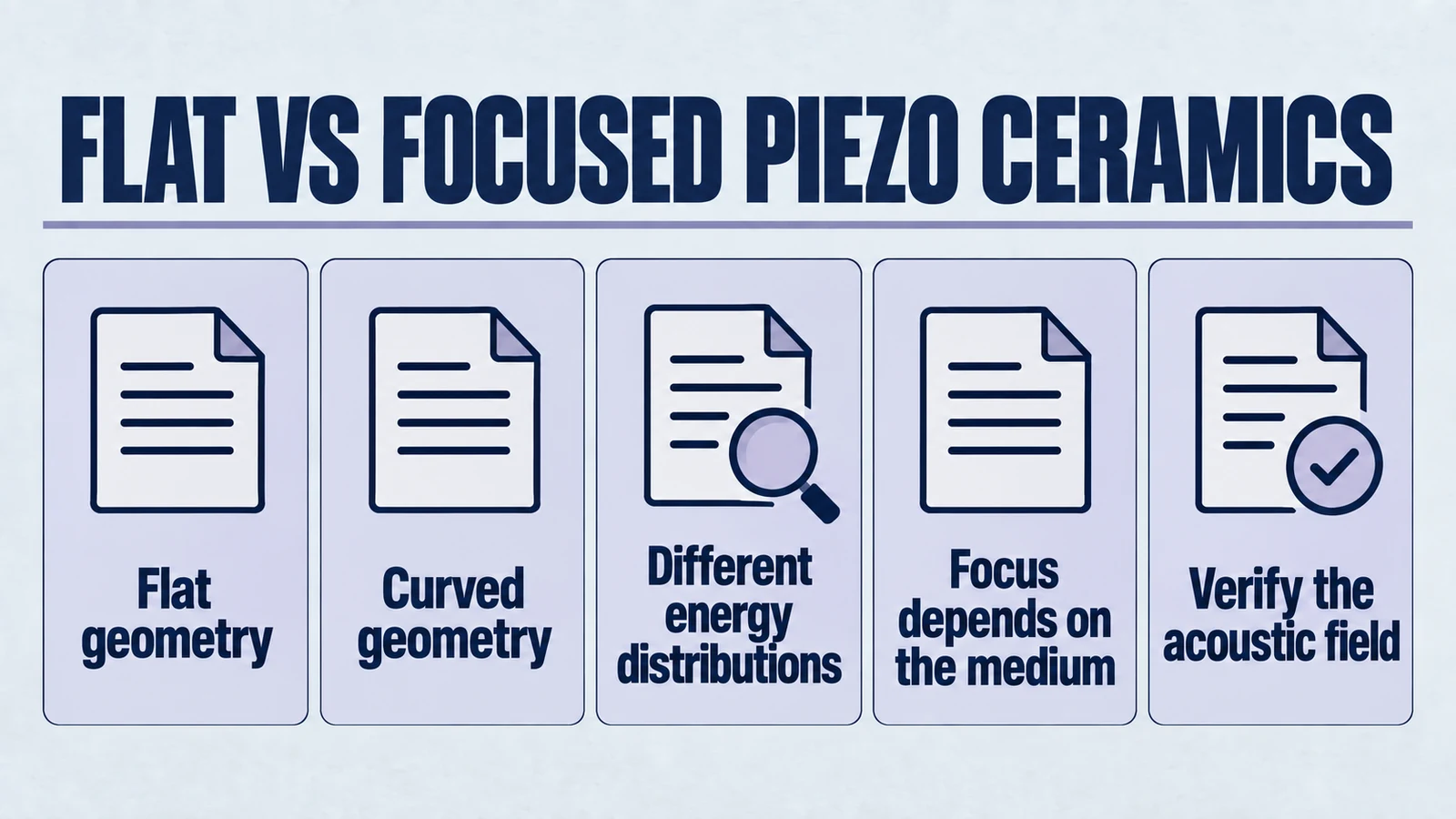
A flat disc tends to radiate a phase front that is approximately planar near the surface. Edge diffraction then creates curvature and side lobes. A custom spherical-cap ceramic (concave) element launches a wavefront that is already “pre-curved.” That is why focusing is achieved primarily by geometry, not by changing the ceramic’s piezoelectric constants.
If you remember only one thing, remember this.
2. Definitions, without the usual traps
Flat piezoelectric ceramics
Typically a disc, ring, plate, or bar with parallel faces. It can be used:
- bare in a liquid tank,
- bonded to a matching layer,
- bonded to a horn (e.g., for welding),
- packaged behind a window.
Flat elements can be “made to focus” with external optics such as acoustic lenses, curved matching layers, reflectors, phased timing, or arrays. But the ceramic itself does not impose focusing.
Focused (spherically curved, spherical-cap) piezoelectric ceramics
A concave ceramic element where one face is a section of a sphere. Commonly called custom spherical-cap piezo ceramics, “bowl,” or “focused” elements.
Two clarifications that avoid months of confusion:
- Spherical-cap is not hemispherical. A hemispherical geometry implies a deep bowl. Most focused ceramics used in practical ultrasonic systems are shallow caps.
- Focusing is geometric. Material properties influence conversion efficiency and losses, but they do not create focusing by themselves.
What “focus” means in practice
The focus is not a mathematical point. It is a 3D region whose size, axial length, and peak pressure depend on:
- aperture diameter or effective aperture,
- radius of curvature,
- wavelength in the medium (frequency, ),
- matching layers, windows, and standoff,
- acoustic loading and nonlinear effects.
A useful mental shortcut is the optics analogy.
- Aperture: the “lens diameter.”
- Radius of curvature: sets the nominal focal distance.
- Wavelength: sets the diffraction limit.
Acoustics is less forgiving than optics. The medium can cavitate, heat up, or load the transducer unpredictably.
3. Acoustic beam formation: how the beam is born
Engineers often compare focused vs flat by looking at “spot size” only. That’s like evaluating antennas by peak RSSI only. Useful, but dangerously incomplete.
3.1 Flat element beam formation
A flat piston-like radiator produces:
- A near field (Fresnel region) where pressure shows strong spatial variation.
- A transition to far field (Fraunhofer) where beam angle is dominated by aperture size vs wavelength.
A practical rule of thumb that helps reason about flat pistons is the near-field length scaling with aperture and wavelength. Different texts express it slightly differently, but the engineering conclusion is consistent.
- Larger aperture at a fixed frequency tends to extend the near field and narrow the far-field beam.
- Higher frequency at a fixed aperture tends to narrow the far-field beam but increases sensitivity to attenuation and tolerances.
Key practical implications:
- Flat elements can deliver strong on-axis pressure in the near field, but the field can be spiky. Small geometry changes, boundary conditions, or mounting stress can shift the spatial pressure pattern.
- Side lobes and edge diffraction become significant when the aperture is not large relative to wavelength.
- In pulse-echo systems, the spatial pattern interacts with receive sensitivity. A “hot” transmit spot does not by itself confirm a clean echo if receive sensitivity is broad or noisy.
3.2 Focused element beam formation
A concave element behaves like a radiator whose emitted wavefronts converge.
- Instead of relying on incidental constructive interference in the near field, the geometry forces a designed convergence.
- The acoustic “focus” is a region with an axial depth of field and a lateral width. Both change with f-number and frequency.
A common trap is assuming that the geometric focal distance equals the “real” focal distance in the assembled system.
- Any matching layer, window, or lens-like stack can shift the effective focus.
- The medium’s sound speed, temperature, and bubble content can shift it again.
Key practical implications:
- Focused elements concentrate acoustic pressure into a smaller region. That is often the reason they exist.
- The beam is usually more predictable than a flat near field. Predictability only holds if curvature and stack are manufactured and assembled consistently.
3.3 External focusing can make flat look “focused”
Flat ceramics are not “unfocused forever.” In many systems, flat ceramics outperform focused ceramics because the focusing function is moved elsewhere.
- A curved matching layer or acoustic lens creates focusing while allowing the ceramic to remain flat.
- A reflector can shape the beam without a curved piezo.
- A phased array can focus and steer electronically, at the cost of complexity and channel count.
The real decision is not “focus or no focus.” It is “where do we place the focusing function, and what does that do to risk.”
4. Energy distribution and focal behavior: where the watts go
4.1 Flat: distributed energy, broader interaction volume
With flat ceramics, acoustic energy is typically spread over a larger region.
What this buys you:
- Better tolerance to target position uncertainty.
- More uniform exposure in cleaning, mixing, atomization (e.g., nebulizers), and general agitation.
- Less sensitivity to small standoff errors.
What it costs:
- Lower peak intensity at any one point, unless you drive harder. That introduces thermal and mechanical risks.
4.2 Focused: concentrated energy, higher local intensity
Focused ceramics push more energy density into the focal zone.
What this buys you:
- Higher local intensity for a given drive level.
- Stronger interaction when the mechanism is intensity-dependent. Examples include localized cavitation, targeted inspection, and defined sensing volumes.
What it costs:
- Sensitivity to alignment. If the target is off-focus, performance may collapse.
- Sensitivity to standoff. Many “mystery failures” are simply the target sitting outside the focal zone.
- Increased risk of local nonlinear effects. Cavitation, bubble shielding, and localized heating may dominate.
A practical translation. Focusing can turn a mostly linear acoustics problem into a nonlinear and failure-prone problem.
4.3 Focus is not free energy. it is energy concentration
A focused element can look “more efficient” because peak pressure is higher. That is not automatically true.
- Focusing concentrates energy spatially. It does not by itself confirm lower losses.
- Many focused designs increase mechanical stress and require thicker bond lines or more complex matching structures. Those can add loss.
Meaningful metrics are application-driven:
- Peak pressure at the target.
- Integrated acoustic power over the relevant interaction volume.
- Stability of those quantities over temperature, tolerances, and lifetime.
5. Trade-offs in efficiency, bandwidth, and stability
5.1 Efficiency
System efficiency is not the same as ceramic efficiency. It includes:
- electrical-to-mechanical conversion,
- mechanical losses in adhesives and backing,
- acoustic coupling to the medium,
- radiation pattern losses. energy you do not use.
Focused advantage: Maximizing energy density in a small region reduces energy outside the target zone.
Flat advantage: Easier mounting, matching, and cooling often make flat designs more efficient at the system level in continuous-duty operation.
A skeptical check. If your gain is mostly peak pressure, verify average acoustic power and drive current.
5.2 Bandwidth
Bandwidth is shaped by the entire resonant system:
- piezo thickness mode,
- backing impedance and damping,
- matching layers,
- acoustic loading,
- mechanical boundary conditions.
Focused ceramics can narrow usable bandwidth when curvature introduces modal interactions or pushes the system toward higher effective Q. The opposite can also happen with careful damping.
Flat ceramics are generally simpler to make broadband, because geometry and boundary conditions are easier to control.
If you need bandwidth and cannot tightly control the stack, flat designs reduce risk.
5.3 Stability. repeatability and drift
Stability has three layers:
- Geometric stability. curvature consistency and bonding effects.
- Resonance stability. modal behavior under load and temperature.
- Field stability. beam pattern repeatability over production and lifetime.
Focused elements are more sensitive to geometric variation because curvature errors map directly into phase errors. Flat elements shift sensitivity to mounting stress, thickness tolerance, and edge conditions.
5.4 Manufacturability and QA
Focused ceramics add variables:
- radius of curvature tolerance,
- cap depth uniformity,
- edge thickness gradients,
- electrode coverage on curved surfaces,
- bond-line variation.
Flat ceramics shift QA toward:
- thickness tolerance,
- parallelism and flatness,
- electrode uniformity,
- mounting consistency.
A revealing test set:
- part-to-part impedance curves,
- on-axis pressure vs distance scans,
- thermal rise under duty cycle.
If a design needs hand tuning, it will not scale.
6. Failure risks and why focusing can make them worse
Choosing focused geometry often means higher local stress and higher local acoustic intensity.
6.1 Mechanical stress concentration
Curved ceramics concentrate stress during:
- pressing or fixturing,
- bonding to a backing,
- clamping,
- thermal cycling.
Rigid adhesive layers and CTE mismatch amplify this risk.
6.2 Thermal runaway and localized heating
Higher intensity at the focus can cause:
- localized heating,
- higher electrical losses as the operating point shifts,
- cavitation-driven erosion,
- feedback loops where acoustic load changes drive conditions.
Focus can move from feature to instability trigger.
6.3 Cavitation and surface damage
Focused beams more easily exceed cavitation thresholds.
That can be intentional. It also causes:
- pitting on nearby surfaces,
- accelerated window wear,
- unpredictable impedance changes from bubble clouds.
Stable-output systems often fail here.
6.4 Depoling and property drift
Both flat and focused ceramics can depole or drift under heat and stress. Focused designs can accelerate:
- microcrack growth,
- gradual property loss,
- resonance shifts.
A common symptom. It worked briefly, then output dropped.
6.5 Mounting failures in flat designs
Flat elements fail differently:
- edge clamping can introduce asymmetric modes,
- uneven preload can split resonances,
- poor backing adhesion can spike Q and temperature.
The lesson is not that flat is appropriate. It is that failure modes differ.
7. When flat ceramics outperform focused designs
This is where many redesigns originate.
7.1 Continuous duty and high average power
Flat geometries win when:
- thermal management dominates,
- the application is not target-localized,
- long-term stability matters.
7.2 “Good enough” beam control with lower risk
Many specs are met with:
- larger flat apertures,
- modest matching-layer shaping,
- reflectors,
- electronic beam steering.
These often deliver better production repeatability.
7.3 Variable target position
Moving targets, variable fluid paths, or uncertain standoff favor flat beams. Forgiveness becomes performance.
7.4 Bandwidth-driven systems
Imaging, NDT, and pulse-echo benefit from:
- simpler matching,
- easier damping,
- repeatable pulse shaping.
Focused probes can work. Sensitivity is higher.
7.5 Integration constraints
Packaging often dominates:
- hygienic windows,
- wear plates,
- compact enclosures.
Flat ceramics behind controlled windows often outperform curved parts in real assemblies.
8. When focused geometry is justified
Focusing is justified when you need:
- a small interaction zone,
- higher local intensity without higher global power,
- spatial selectivity,
- geometric focusing where electronics are impractical.
Examples include fixed-position inspection and intensity-driven mechanisms. Treat focusing as a system architecture choice, not a part swap.
9. A decision checklist
- Required interaction volume. Broad field favors flat.
- Target position control. Drift punishes focus.
- Intensity-threshold mechanisms. Focus helps but destabilizes.
- Bandwidth needs. Limited damping budget favors flat.
- Production tolerance reality. Focus demands tighter control.
- Failure consequences. Focused designs fail faster when misused.
- Placement of focusing function. Geometry, optics, or electronics.
- Production validation. If you cannot measure it, you are guessing.
10. Compact comparison table
| Dimension | Flat ceramics | Focused spherical-cap ceramics |
|---|---|---|
| Beam formation | Broad. near field can be spiky | Converging by geometry. smaller focal region |
| Alignment tolerance | High | Lower. sensitive to standoff and offset |
| Peak intensity | Lower without higher drive | Higher at focus |
| Continuous duty | Often better | Challenged by local stress |
| Bandwidth risk | Easier to make broadband | More sensitive to stack |
| Manufacturing sensitivity | Thickness, flatness | Curvature, bond uniformity |
| Failure triggers | Mounting stress, delamination | Stress concentration, cavitation |
| Best fit | Uniform processes, variable targets | Fixed targets, spatial selectivity |
11. The honest takeaway
If you need predictable, forgiving acoustic output over a wide region. Flat ceramics are often the better engineering choice, even when focused parts look attractive on paper.
If you need spatial selectivity or intensity concentration and can control alignment, stack design, and manufacturing variation. Focused geometry can unlock performance you cannot get from a flat element alone.
Neither is best. Geometry is the lever. Material is the constraint set.
Engineering decision notes
PZT material and ceramic selection
Use this article when the choice is not just a shape, but a material tradeoff between sensitivity, loss, coupling, stability, and operating field. For "Focused vs Flat Piezoelectric Ceramics: Why Geometry Matters More Than Material", the practical value is in turning the topic into a measurable selection or sourcing decision.
YJ Piezo coordinates PZT ceramic projects with manufacturing support, so material formulation, sintering, polarization, electrode process, and outgoing inspection can be reviewed against the final application.
Selection checks
- Separate sensing needs from high-power actuation needs before comparing d33 or coupling values.
- Check dielectric loss, Qm, Curie temperature, aging behavior, and operating field against the real duty cycle.
- Confirm whether the application needs standard PZT grades or a custom formulation and geometry.
Failure risks
- Choosing only the highest d33 can create heat, drift, or depolarization risk in power ultrasonics.
- A ceramic that performs well in free measurement can fail once bonded, clamped, or loaded.
- Material substitutions without batch testing can change capacitance, resonance, and system tuning.
RFQ details
- Is the part used for sensing, actuation, atomization, cleaning, welding, or measurement?
- What field strength, temperature, duty cycle, and mechanical load will the ceramic see?
- Which values must be controlled: d33, capacitance, resonance, impedance, Qm, or dimensional tolerance?
Relevant YJ Piezo pages
- PZT Material Hub
Material grades and application tradeoffs
- Piezoelectric Ceramics
Shapes and ceramic manufacturing options
- PZT Material Supplier Hub
Material control, grade selection, and sourcing support
Application FAQ
- Is the highest d33 always the best PZT choice?
- No. High d33 can be useful for sensitivity, but high-power ultrasonic systems often need lower loss, higher Qm, better thermal stability, and safer operation under field and stress.
- What makes PZT material selection different from catalog buying?
- The right PZT choice depends on geometry, load, drive field, duty cycle, temperature, and inspection targets. A catalog value is only useful when it is tied to the final assembly conditions.