
Piezo Tubes: The Ultimate Guide to 360° Ultrasonic Sensing and Actuation
Introduction: Beyond the Beam—The Critical Need for 360° Situational Awareness
In the world of advanced sensing and actuation, ultrasound is a cornerstone technology. For decades, engineers have harnessed the power of piezoelectric transducers—devices that masterfully convert electrical energy into mechanical vibrations and back again—to see the unseen, measure the infinitesimal, and perform tasks with microscopic precision. From medical imaging to industrial quality control, these components are the engines of modern technology.
Traditionally, ultrasonic technology has been perceived as a highly directional tool, much like a flashlight cutting a focused beam through the darkness. A standard flat, disc-shaped transducer emits a column of acoustic energy, ideal for point-to-point measurements or forward-looking imaging. While immensely useful, this directional paradigm has inherent limitations. It provides a narrow, linear perspective, leaving vast areas of the surrounding environment unmonitored. What happens when the challenge isn't to see what's directly ahead, but to understand everything that's all around?
This is the critical engineering problem that a growing number of advanced applications face. Consider the immense challenge of ensuring the structural integrity of thousands of miles of oil and gas pipelines. A simple forward-looking sensor is insufficient; what's required is a complete, 360-degree inspection of the pipe's inner wall to detect corrosion or cracks. Imagine an autonomous underwater vehicle (AUV) navigating the murky, unpredictable depths of the ocean. It needs total situational awareness not just to avoid obstacles in its path, but to detect targets or map its surroundings from every angle simultaneously. Or picture a cardiologist guiding a catheter through a delicate artery. A two-dimensional X-ray shadow is not enough; a real-time, cross-sectional view of the vessel wall is needed to accurately assess plaque and deploy stents.
Product path for this search intent
Match the article topic to the right YJ Piezo product page
Use this article when the choice is not just a shape, but a material tradeoff between sensitivity, loss, coupling, stability, and operating field. For "Piezo Tubes: The Ultimate Guide to 360° Ultrasonic Sensing and Actuation", the practical value is in turning the topic into a measurable selection or sourcing decision.
- PZT Material Hub
Material grades and application tradeoffs
- Piezoelectric Ceramics
Shapes and ceramic manufacturing options
- PZT Material Supplier Hub
Material control, grade selection, and sourcing support
In these scenarios, a simple "flashlight" beam is inadequate. What is required is a "lightbulb"—a source of energy that radiates outwards uniformly, illuminating the entire environment at once. This is precisely the capability that the piezoelectric tube, or cylinder, delivers. By fundamentally re-imagining the geometry of the transducer, the piezo tube unlocks a new dimension of sensing: complete, 360-degree ultrasonic emission and reception.
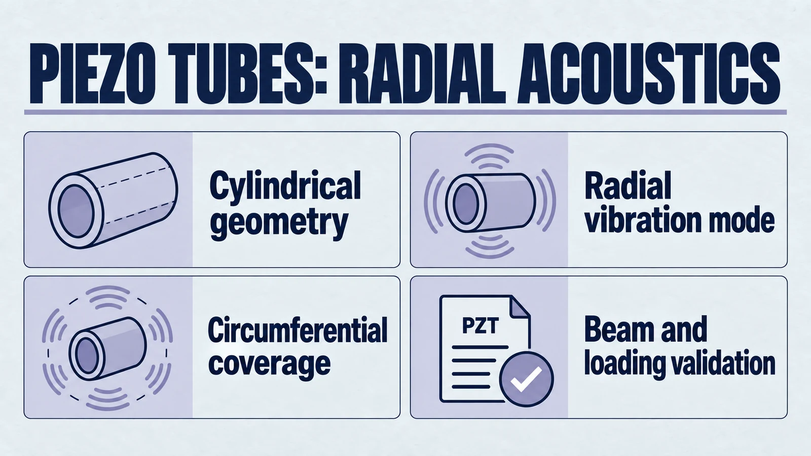
This geometry moves beyond linear spot-checking and can support broader circumferential awareness. Piezoelectric tubes are useful components in non-destructive testing, underwater acoustics, and advanced diagnostic-device architectures where the finished system is designed and validated around radial-mode behavior. This guide explains the physics, engineering advantages, and application constraints of cylindrical PZT geometry.
The Physics of Omnidirectional Ultrasound: A Deep Dive into Radial Mode Vibration
To appreciate the unique power of a piezo tube, one must first understand the fundamental principle that governs its operation: the inverse piezoelectric effect. At its core, this phenomenon describes how certain ceramic materials, when subjected to an electric field, physically deform—expanding or contracting in a predictable manner. When an alternating current (AC) voltage is applied, the material is forced to vibrate at the same frequency, creating a series of pressure waves in the surrounding medium. These pressure waves are what we know as sound, and when their frequency exceeds the range of human hearing (typically above 20 kHz), they are classified as ultrasound.
While all piezoelectric transducers leverage this effect, the shape of the transducer is the primary determinant of how it vibrates and, consequently, the shape of the acoustic field it generates. This is where the critical distinction between a conventional flat disc and a piezoelectric tube emerges. The geometry of the component is not a simple matter of packaging; it dictates the fundamental physics of the wave propagation.
A conventional flat, disc-shaped transducer primarily vibrates in what is known as the "thickness mode." When voltage is applied across its flat faces, the disc expands and contracts along its thickness axis. This motion is analogous to a piston, pushing a column of air or liquid directly forward. The result is a well-defined, directional beam of ultrasonic energy. This is highly effective for applications requiring a focused line of sight, such as standard medical ultrasound probes or distance-ranging sensors.
A piezoelectric tube, however, operates on a completely different principle: radial mode vibration. A piezo tube is a hollow cylinder with electrodes typically applied to its inner and outer curved surfaces. When an AC voltage is applied across the wall of the tube, the electric field causes the ceramic material to expand and contract along its radius. This creates a "breathing" motion where the entire diameter of the tube rhythmically increases and decreases.
This radial expansion and contraction pushes pressure waves outward around the radial plane. Instead of a focused forward beam, the tube can generate a near-omnidirectional cylindrical field when the geometry, electrodes, and mounting are designed correctly. This mode of vibration allows a single, stationary piezoelectric tube to interrogate a broad circumferential area.
The physics of this vibration can be complex. In reality, the motion of a finite-length cylinder is a "coupled vibration," meaning the primary radial mode interacts with other vibrational modes, such as longitudinal (lengthwise) and even torsional modes. The aspect ratio of the tube—its length relative to its diameter and wall thickness—plays a crucial role in determining the resonant frequencies and the efficiency of the desired radial vibration. Therefore, designing a piezo tube for a specific application is a sophisticated engineering task. It requires a deep understanding of material properties and vibrational mechanics to optimize the geometry, ensuring that the dominant mode of vibration is the radial one, maximizing the energy projected into the desired 360-degree field.
This physical distinction is important for design engineers. A disc transducer can be scanned mechanically or arranged in arrays, but a cylindrical element is often the more direct geometry when the target field is circumferential. For applications where 360-degree awareness is the goal, the piezoelectric tube is a purpose-built option that still requires full acoustic and mechanical validation.
The Engineering Advantage: Where a Cylindrical Transducer Helps
Moving from the underlying physics to practical implementation, the unique radial vibration of a piezo tube translates into a suite of powerful engineering advantages. For designers of advanced sensor systems, choosing a cylindrical transducer over a conventional flat disc is a strategic decision that can dramatically simplify design, enhance performance, and unlock new capabilities.
The most significant advantage is the ability to cover a broad circumference from a single, stationary component. A flat disc may require rotation or multiple elements to scan 360 degrees. A piezoelectric tube can reduce that mechanical complexity by generating a radial field around the cylinder, helping designers build more compact sensing assemblies when the acoustic path supports it.
Secondly, the cylindrical geometry offers a large radiation surface area, which is critical for applications requiring high acoustic power and efficiency. In fields like sonar, the ability to transmit a strong, clear signal over long distances is paramount. The expansive surface of a tube allows it to displace a greater volume of the medium (e.g., water) with each vibration, which can affect radiated power at a specified surface velocity and load; more area alone does not establish superior useful-output efficiency. This means more of the input electrical energy is converted into useful sound energy, a crucial factor for battery-powered devices like autonomous vehicles or remote sensors.
Furthermore, the inherent structural integrity and simplicity of the cylindrical shape make piezoelectric tubes exceptionally robust and easy to integrate. Their simple, strong form factor is ideal for harsh environments, such as the high pressures and temperatures found in downhole oil and gas inspection tools. The shape also lends itself to seamless integration into other cylindrical assemblies, such as medical catheters or the housings for underwater hydrophones, simplifying manufacturing and improving the reliability of the final product.
Finally, like other piezoelectric ceramic components, tubes offer tremendous versatility in design and customization. They can be manufactured from a wide range of lead zirconate titanate (PZT) materials—from "soft" ceramics engineered for high sensitivity in sensor applications to "hard" ceramics designed for high power handling in transmitters. Moreover, their dimensions—diameter, wall thickness, and length—can be precisely tailored to achieve specific resonant frequencies, power levels, and spatial constraints. This allows engineers to develop a fully customized transducer optimized for the unique demands of their application, whether it's a high-frequency, high-resolution medical device or a low-frequency, long-range sonar system.
| Feature | Piezoelectric Tube/Cylinder | Flat Piezoelectric Disc |
|---|---|---|
| Primary Emission Pattern | 360° Radial (Omnidirectional) | Directional (Forward Beam) |
| Dominant Vibration Mode | Radial Mode ("Breathing") | Thickness Mode ("Piston") |
| Typical Coverage Area | Complete Circumference | Focused Spot/Cone |
| Ideal Applications | Pipeline inspection, sonar, hydrophones, IVUS catheters, flow metering | Medical imaging, NDT flaw detection, distance sensors, actuators |
| Suitability for In-Pipe Inspection | Excellent: Provides full, simultaneous coverage of the pipe wall from a central axis. | Poor: Requires complex mechanical rotation to scan the full circumference, which is often impractical. |
This comparative analysis leads to a clear conclusion: while flat discs excel at directional tasks, the piezoelectric tube is often the better geometry for applications demanding complete, real-time, 360-degree ultrasonic awareness.
In-Depth Applications: Piezo Tubes in Action Across Industries
The theoretical advantages of piezoelectric tubes are powerfully demonstrated in their real-world applications across some of the most demanding technological fields. The fundamental capability of generating a 360-degree ultrasonic field is a platform technology, meaning the same core principle is adapted across vastly different scales and environments to solve the same essential problem: the need for complete circumferential data. From inspecting miles of industrial pipeline to imaging the delicate interior of a human artery, piezo tubes are the critical enabling component.
Non-Destructive Testing (NDT): Achieving 360° Flaw Detection in Pipelines and Boreholes
In the oil and gas, power generation, and manufacturing industries, the integrity of pipelines, boreholes, and other cylindrical components is a matter of critical safety and economic importance. Non-destructive testing (NDT) is the practice of inspecting these structures for defects like corrosion, cracks, inclusions, or variations in wall thickness without causing damage. The challenge lies in inspecting the entire inner surface of a long pipe, a task for which traditional methods are slow and incomplete.
This is where ultrasonic inspection tools, often called "pigs," come into play. These sophisticated devices travel through the interior of a pipeline, using sensors to create a detailed map of its condition. The most advanced of these tools rely on ultrasonic technology, and piezoelectric tubes are central to their design. The pig is equipped with one or more rings of ultrasonic transducers that are arranged to provide complete 360-degree circumferential coverage.
As the pig moves, the piezo tubes emit short ultrasonic pulses in a radial direction. These sound waves travel through a coupling medium (typically the liquid product in the pipeline) and strike the inner wall of the pipe. A portion of the wave is reflected back to the transducer as an "entry-echo." The rest of the wave enters the pipe wall, travels through it, and is reflected off the outer wall, returning as a "back-wall echo."
The system's electronics precisely measure the "time-of-flight" for these two echoes. By knowing the speed of sound in the coupling medium and the pipe material, the device can perform two crucial calculations in real-time:
- Distance to the Inner Wall: The time for the entry-echo to return provides a precise measurement of the pipe's internal diameter, allowing for the detection of dents, buckles, or other geometric deformities.
- Wall Thickness: The time delay between the entry-echo and the back-wall echo provides a direct, highly accurate measurement of the pipe wall's thickness. This allows for the precise mapping of metal loss due to corrosion or erosion.
Because the piezoelectric tubes provide a complete 360-degree field, broad azimuthal coverage is possible, but angle-resolved inspection requires circumferential channels, scanning, beamforming or another angular encoding. One omnidirectional channel does not establish a full map or absence of blind spots. The high sensitivity of piezoelectric ceramics allows for the detection of even minute defects, and this ultrasonic method is one of the few technologies capable of reliably identifying mid-wall features like laminations, which are invisible to many other inspection techniques.
Underwater Acoustics: The Heart of Modern Sonar and Hydrophones
The opaque nature of water makes sound the most effective medium for underwater sensing, navigation, and communication. From military defense to marine biology and commercial fishing, the ability to "see" with sound is essential. Piezoelectric tubes are the core technology in two key types of underwater acoustic devices: active sonar systems and passive hydrophones.
Active Sonar Projectors: An active sonar system works by transmitting a pulse of sound—a "ping"—and listening for the echoes that bounce off underwater objects. For applications requiring omnidirectional awareness, such as obstacle avoidance for an Autonomous Underwater Vehicle (AUV) or general surveillance, a piezoelectric tube is the ideal sound source. Its ability to project a powerful, uniform 360-degree acoustic wave allows it to interrogate the entire surrounding environment with a single ping. A one-channel broad-azimuth ping does not by itself resolve target direction or form a complete image; use the complete array/scanning and processing architecture. The high power capacity and electroacoustic efficiency of cylindrical transducers are particularly vital here, enabling long-range detection while minimizing power drain on the vehicle's batteries.
Passive Hydrophones: A hydrophone is essentially an underwater microphone, designed to listen for sounds rather than create them. They are used for a vast range of applications, from listening for marine life to detecting distant acoustic signatures. For many of these applications, omnidirectional reception is crucial. A sensor needs to detect sound from different directions with controlled sensitivity. A small, single piezoelectric tube can act as a compact omnidirectional receiver. As an incoming pressure wave from any direction compresses the cylinder, the piezoelectric effect generates a corresponding electrical voltage.
Medical Technology: Intravascular Imaging with IVUS
Perhaps the most remarkable application of 360-degree ultrasonic sensing occurs on a microscopic scale: inside the human cardiovascular system. For decades, the standard for visualizing coronary arteries has been angiography, an X-ray technique that provides a two-dimensional silhouette, or "luminogram," of the vessel. While useful, angiography cannot see the vessel wall itself and often underestimates the extent of atherosclerosis (plaque buildup).
Intravascular Ultrasound (IVUS) technology was developed to overcome this limitation. An IVUS system uses a tiny catheter, thin enough to be guided through a arteries, with a miniature ultrasonic transducer at its tip. This transducer provides a real-time, 360-degree, cross-sectional image of the artery from the inside out, revealing not just the open lumen but the thickness and characteristics of the plaque buildup on the arterial wall.
The enabling technology at the heart of the IVUS catheter is a custom-designed piezoelectric transducer engineered for 360-degree imaging. There are two primary designs:
- Mechanical IVUS: This system uses a single, tiny piezoelectric element that is mechanically rotated at high speed (e.g., 1800 RPM) by a flexible driveshaft inside the catheter. As it spins, it rapidly sweeps a beam of ultrasound in a 360-degree arc, building up a complete cross-sectional image.
- Solid-State IVUS: This design uses a circumferential array of dozens of miniature piezoelectric elements (e.g., 64) fixed around the catheter tip. These elements are activated sequentially by sophisticated electronics to create a composite 360-degree image without any moving parts.
In both cases, the functional principle is the same: to achieve a complete circumferential view. The high-frequency ultrasound (typically 20-40 MHz) required for the necessary image resolution is generated by these precisely manufactured piezoelectric components.
Engineering Your Solution: Selecting the Right Piezo Tube for Optimal Performance
Understanding the power and versatility of piezoelectric tubes is the first step. The next, more critical step for any engineer or product designer is translating that understanding into a functional, reliable, and high-performance product. The selection and specification of a piezo tube is not a one-size-fits-all process; it is a nuanced engineering decision that requires careful consideration of the application's unique demands. Partnering with a knowledgeable and experienced manufacturer is key to navigating these choices and achieving an optimal design.
Several key factors must be considered when engineering a solution:
1. Piezoelectric Material Selection
The ceramic material itself is the heart of the transducer. PZT materials are generally categorized as "hard" or "soft," each with distinct properties:
- Hard PZT: These materials are characterized by their ability to withstand high electrical drive and mechanical stress within qualified field/stress/temperature limits; hard PZT is not immune to depolarization. They exhibit lower mechanical loss, making them ideal for high-power transmitting applications like sonar projectors or ultrasonic cleaning, where generating a strong acoustic field is the primary goal.
- Soft PZT: These materials offer higher sensitivity, a higher dielectric constant, and a higher piezoelectric coupling factor. Charge response, voltage sensitivity and power efficiency are different measures. Select the relevant d/g/k coefficients, mode and readout; higher permittivity or coupling alone does not establish complete-device efficiency. They are the preferred choice for sensor applications, such as hydrophones or the receiving elements in NDT probes, where detecting the faintest possible signal is critical.
2. Geometric Considerations and Frequency
The physical dimensions of the tube—its outer diameter, inner diameter (wall thickness), and length—are not arbitrary. They are precisely calculated to determine the transducer's resonant frequency.
Frequency and Resolution/Range: There is a fundamental trade-off in all ultrasonic applications. Higher frequencies produce shorter wavelengths, which allow for greater measurement resolution and the ability to detect smaller defects or features. This is why medical IVUS systems operate at very high frequencies. However, high-frequency sound attenuates more quickly in a medium, limiting its effective range. Lower frequencies penetrate much further, making them suitable for long-range applications like deep-water sonar, but at the cost of lower resolution.
Optimizing Dimensions: The resonant frequency of the radial mode is primarily a function of the tube's diameter and wall thickness. An experienced manufacturer can work with your target frequency and performance requirements to engineer the precise dimensions needed to optimize the radial vibration and maximize the transducer's output and sensitivity.
3. The Importance of Quality and Customization
The performance of an advanced system is only as good as its weakest component. For piezoelectric transducers, achieving consistent, reliable performance requires exceptionally high-quality materials and precision manufacturing. Tight tolerances on dimensions, uniform material properties, and flawless electrode application are essential for ensuring that the final component operates at its predicted frequency and efficiency.
Because most advanced applications have unique constraints, off-the-shelf components may not match the target acoustic and packaging requirements. A customized piezo tube can be tailored in material, size, shape, and electrode configuration so the device team can match the transducer more closely to its electronics, housing, and operating environment.
Partner with the Experts: Unlock Next-Level Innovation
The process of designing and integrating a piezoelectric tube is often a collaborative one. The success of a final product, whether it's a medical device program or a critical piece of industrial infrastructure, depends on a deep partnership between the system designer and the component manufacturer.
If you are facing a complex sensing or actuation challenge that demands 360-degree awareness, our team of experts is ready to assist. We specialize in partnering with engineers to understand their unique application requirements and developing custom piezoelectric solutions that deliver strong performance and reliability.
Contact us to discuss your project and discover how the power of piezoelectric tubes can unlock the next level of innovation for your application.
Engineering decision notes
PZT material and ceramic selection
Use this article when the choice is not just a shape, but a material tradeoff between sensitivity, loss, coupling, stability, and operating field. For "Piezo Tubes: The Ultimate Guide to 360° Ultrasonic Sensing and Actuation", the practical value is in turning the topic into a measurable selection or sourcing decision.
YJ Piezo coordinates PZT ceramic projects with manufacturing support, so material formulation, sintering, polarization, electrode process, and outgoing inspection can be reviewed against the final application.
Selection checks
- Separate sensing needs from high-power actuation needs before comparing d33 or coupling values.
- Check dielectric loss, Qm, Curie temperature, aging behavior, and operating field against the real duty cycle.
- Confirm whether the application needs standard PZT grades or a custom formulation and geometry.
Failure risks
- Choosing only the highest d33 can create heat, drift, or depolarization risk in power ultrasonics.
- A ceramic that performs well in free measurement can fail once bonded, clamped, or loaded.
- Material substitutions without batch testing can change capacitance, resonance, and system tuning.
RFQ details
- Is the part used for sensing, actuation, atomization, cleaning, welding, or measurement?
- What field strength, temperature, duty cycle, and mechanical load will the ceramic see?
- Which values must be controlled: d33, capacitance, resonance, impedance, Qm, or dimensional tolerance?
Relevant YJ Piezo pages
- PZT Material Hub
Material grades and application tradeoffs
- Piezoelectric Ceramics
Shapes and ceramic manufacturing options
- PZT Material Supplier Hub
Material control, grade selection, and sourcing support
Application FAQ
- Is the highest d33 always the best PZT choice?
- No. High d33 can be useful for sensitivity, but high-power ultrasonic systems often need lower loss, higher Qm, better thermal stability, and safer operation under field and stress.
- What makes PZT material selection different from catalog buying?
- The right PZT choice depends on geometry, load, drive field, duty cycle, temperature, and inspection targets. A catalog value is only useful when it is tied to the final assembly conditions.