
The Engineering of Silence and Sound: A Comprehensive Treatise on Mode Coupling in Piezoelectric Ceramics
1. Introduction: The Complexity of the "Simple" Resonator
In the specialized discipline of electroacoustic engineering, the idealized concept of a piezoelectric resonator—a ceramic element vibrating purely in a single dimension—is a theoretical luxury that rarely survives the rigors of physical reality. For the transducer designer, the challenge is not merely to excite a vibration but to confine it. When we apply an alternating electric field across a polarized ferroelectric ceramic, we initiate a complex interplay of electromechanical forces that refuse to remain isolated along a single axis. This phenomenon, known as Mode Coupling, represents the single most significant hurdle in the design of high-precision ultrasonic devices, sensors, and actuators.
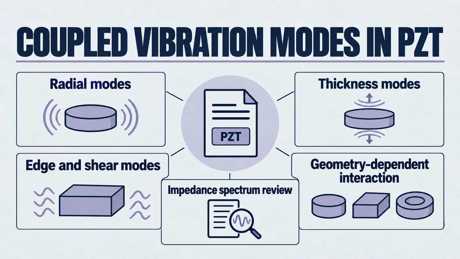
For engineers and designers working with materials such as Lead Zirconate Titanate (PZT), understanding mode coupling is not an academic exercise; it is a necessity for survival in a market demanding ever-higher efficiency and signal fidelity. Whether one is designing a focused ultrasound equipment transducer, a sensitive hydrophone for underwater acoustics, or a precision actuator for semiconductor lithography, the presence of spurious modes—unwanted vibrations coupled to the primary mode—can lead to impedance spectrum distortion, reduced electromechanical conversion efficiency, and serious mechanical failure due to stress concentrations. The "simple" act of driving a PZT disc at its thickness resonance is, in fact, an invitation to a chaotic symphony of radial, edge, and shear modes that must be orchestrated with precision.
This engineering guide, prepared for the technical community at Yujie Piezo, explains mode coupling in piezoelectric ceramics. It covers the theoretical foundations of coupled vibration, the spectral behavior of finite geometries, and mitigation strategies ranging from geometrical contouring to piezocomposite engineering. By combining research concepts with contemporary finite element analysis (FEA) practice, it helps turn transducer design into a more navigable engineering process.
Product path for this search intent
Match the article topic to the right YJ Piezo product page
Use this article when the choice is not just a shape, but a material tradeoff between sensitivity, loss, coupling, stability, and operating field. For "The Engineering of Silence and Sound: A Comprehensive Treatise on Mode Coupling in Piez...", the practical value is in turning the topic into a measurable selection or sourcing decision.
- PZT Material Hub
Material grades and application tradeoffs
- Piezoelectric Ceramics
Shapes and ceramic manufacturing options
- PZT Material Supplier Hub
Material control, grade selection, and sourcing support
1.1 The Ideal vs. The Real
Linear piezoelectric constitutive equations describe local material relations and do not require infinite geometry. Particular analytical modal solutions impose idealized geometry and boundary conditions. A "thickness mode" calculation assumes a plate of infinite lateral extent, where the strain is strictly uniaxial and lateral boundaries are effectively at infinity. Conversely, a "radial mode" calculation assumes a disc of infinitesimal thickness, reducing the problem to a two-dimensional plane stress state. In these idealized scenarios, the resonant frequencies are governed by simple frequency constants (, , ) and the linear dimensions of the ceramic.
However, real-world ceramic elements—discs, plates, rods, and tubes—possess finite dimensions in all directions. The Poisson effect, a fundamental property of elastic solids, dictates that compression in one direction inevitably induces expansion in orthogonal directions. In a piezoelectric solid, this mechanical coupling is exacerbated by dielectric coupling, where the electric displacement vector is also tied to the multi-axial strain state. Consequently, a disc driven at its thickness resonance will inevitably excite radial motions. When the harmonics of these radial motions coincide with the fundamental thickness frequency, mode coupling occurs, leading to energy splitting and performance degradation.
The deviation from the ideal 1D piston model is not merely a nuisance; it is a fundamental characteristic of the medium. As noted in classic literature, the mathematical effort involved in solving the full 3D equations for a finite cylinder is enormous, often yielding transcendental equations with roots that defy simple analytical expression. Tiersten (1969) demonstrated that the frequencies of thickness modes are given by the roots of complex trigonometric functions, while the radial modes follow Bessel functions. The interaction between these mathematical descriptions in a finite body leads to "mode repulsion" and the breakdown of simple frequency constants.
2. Theoretical Foundations of Piezoelectric Vibration
To master mode coupling, one must first appreciate the governing physics that bind the electrical and mechanical domains. The piezoelectric effect is described by coupled equations relating the stress (), strain (), electric field (), and electric displacement (). These constitutive equations are the bedrock upon which all understanding of mode coupling is built.
2.1 Constitutive Equations and Tensor Mechanics
The interaction in a piezoelectric ceramic is quantified by piezoelectric constants () and, crucially, the electromechanical coupling factors (). The complexity arises because these are not scalar values but tensors. The material properties depend heavily on the direction of the applied field relative to the poling axis.
For a standard PZT ceramic poled in the thickness direction (defined as the Z-axis or '3' direction), the coupling is described by the piezoelectric charge constant tensor .
- (Longitudinal Coefficient): This describes the strain developed in the poling direction per unit of electric field applied in the same direction. It is the primary driver for thickness mode transducers and longitudinal actuators.
- (Transverse Coefficient): This coefficient describes the strain developed in the lateral direction (axes 1 or 2) when a field is applied in the 3-direction. Crucially, is typically negative, meaning that a positive field which expands the thickness () will simultaneously contract the diameter. This inherent antagonism is the root of mode coupling. The material wants to deform in all directions simultaneously.
- (Shear Coefficient): This relates shear strain to a transverse electric field. While often ignored in pure thickness-drive applications, shear modes can be excited parasitically if the electric field lines bend near the edges of electrodes or if the material poling is non-uniform.
The strength of these interactions is measured by the electromechanical coupling factor, . It is vital to understand that is not an efficiency metric in the traditional sense (power out / power in). Rather, represents the ratio of stored mechanical energy to total input electrical energy (or stored electrical energy to total input mechanical energy) in a quasi-static cycle.
| Coupling Factor | Definition | Physical Significance | Typical PZT-5H Value |
|---|---|---|---|
| Longitudinal | Coupling for vibration parallel to poling (infinite rod). | ~0.75 | |
| Transverse | Coupling for lateral vibration (long bar). | ~0.44 | |
| Planar | Coupling for radial vibration in a thin disc (combines in 2D). | ~0.65 | |
| Thickness | Effective coupling for a plate of infinite lateral extent. | ~0.50 | |
| Shear | Coupling for shear vibration. | ~0.68 |
A critical insight from Table 1 is that (planar coupling) is often significantly higher than and comparable to . This means that a PZT disc is extremely efficient at converting electrical energy into radial vibration—often more efficient than converting it into the desired thickness vibration if the geometry allows it. This high efficiency of the "unwanted" mode is what makes mode coupling such a persistent threat.
2.2 The Physics of Dispersion and Waveguides
Mode coupling is fundamentally a wave propagation issue within a bounded medium. A PZT disc acts as a cylindrical waveguide. When we excite the ceramic, we launch elastic waves that reflect off the boundaries (the top/bottom surfaces and the cylindrical sidewall). These reflections create standing waves, which we perceive as resonances.
Elastic and piezoelectric resonators can exhibit crossings or avoided crossings. Interacting modes may hybridize and exchange character, while symmetry or decoupling may permit a crossing. Determine the behavior from the governing eigenproblem and measured mode shapes; frequency proximity alone does not prove interaction.
This repulsion is the spectral fingerprint of mode coupling. The mathematically rigorous analysis by Tiersten (1969) showed that the resonant frequencies are roots of transcendental equations involving the material constants and dimensions. The complexity of these equations reveals why simple "frequency constants" fail when modes interact. In the coupling region, the vibration character changes continuously from one mode type to another, creating hybrid modes that are neither pure thickness nor pure radial.
2.3 Limitations of 1D Modeling (The Mason Model)
For decades, engineers have relied on 1D equivalent circuit models, such as the Mason model or the KLM (Krimholtz, Leedom, and Matthaei) model, to simulate piezoelectric devices. These models represent the transducer as an acoustic transmission line, treating the piezoelectric element as a piston source.
While powerful for initial sizing and electrical matching, 1D models possess a fatal flaw regarding mode coupling: they assume infinite lateral dimensions (or zero lateral coupling). They utilize a "clamped" permittivity and stiffened elastic constants to approximate the thickness mode, effectively ignoring the lateral boundary conditions.
- The Negative Capacitance Artifact: In the Mason model, a negative capacitor is often used to represent the electromechanical coupling. While mathematically convenient for circuit solvers, this component has no direct physical analogue and often obscures the complex interplay of secondary modes. It represents the "intercoupling effect," but fails to predict the frequencies of spurious modes.
- Blind Spots: A distributed one-dimensional thickness model can represent thickness overtones, but cannot predict lateral modes or finite-boundary coupling excluded from that model. It is distinct from a single-branch lumped approximation. Validate the model for the geometry and frequency interval of interest.
3. The Geometry of Resonance: Aspect Ratios and Mode Charts
The single most critical parameter in the design of a piezoelectric resonator is the aspect ratio, typically defined as the ratio of the lateral dimension (Diameter or Width ) to the thickness ( or ). The behavior of the resonator changes drastically as this ratio evolves, moving through distinct regimes of vibration.
3.1 Frequency Constants and Dimensions
The resonance frequency is inversely proportional to the governing dimension. This linear relationship is described by Frequency Constants (), which are material-specific values derived from the sound velocity in the medium.
- Radial Mode: . As the diameter shrinks, the radial frequency shoots up.
- Thickness Mode: . As the thickness decreases, the thickness frequency increases.
- Longitudinal Mode: . For rods and bars.
The "danger zone" for mode coupling arises when the geometries align such that the frequency of the radial mode (or one of its energetic harmonics) coincides with the fundamental thickness mode frequency. Since and are often similar in magnitude (e.g., ~2000 Hz-m for PZT-4), a disc where (a cylinder) will have its fundamental radial and thickness resonances at nearly the same frequency. For guidance on selecting the right geometry, see our piezoelectric ceramics geometry guide. This is particularly important when designing components like rings, tubes, or rectangular plates.
3.2 The Shaw and Ikegami Mode Charts
The historical mapping of these danger zones was achieved experimentally by Shaw (1956) and later refined computationally and experimentally by Ikegami et al. (1974) and Guo (1990). These researchers produced "Mode Charts"—plots of the frequency–thickness product (with units of velocity when SI units are used) () against the aspect ratio ().
These charts are the navigational maps for the transducer engineer, revealing the complex topology of vibrational modes:
3.2.1 The Plateau (D/T < 1)
For tall rods or cylinders where the diameter is smaller than the thickness (aspect ratio < 1), the primary mode of vibration is the Longitudinal Length Mode (). The boundary conditions here are dominated by the stress-free sidewalls.
- Vibration Character: The rod extends and contracts along its length. The lateral contraction is uniform.
- Coupling: The effective coupling coefficient () is high, approaching the material's (approx 0.70 for PZT-5H). Spurious modes in this region are typically flexural or bending modes, which are generally weak if the rod is symmetrically driven.
3.2.2 The Coupling Region (D/T ≈ 1 - 5)
This is the most treacherous region for transducer design. As the diameter increases relative to thickness, the radial modes drop in frequency and begin to "pass through" the thickness resonance frequency band.
- The Crossing of R2, R3, R4: The fundamental radial mode drops well below the thickness mode. However, the second (), third (), and fourth () harmonics of the radial mode traverse the thickness mode frequency.
- Coincidence Points: At specific aspect ratios, the lines intersect. For example, at , the first radial mode interacts strongly with the thickness mode. At , the (0,2) radial mode crosses the thickness mode.
- Consequences: At these crossing points, the impedance spectrum splits. The "thickness mode" ceases to exist as a distinct entity; energy is shared equally between thickness and radial motion. The drops precipitously, and the mechanical quality factor () degrades. This region is often called the "Dead Zone" for pure mode applications.
3.2.3 The Thin Disc Region (D/T > 10)
As the disc becomes very thin, the fundamental radial mode () moves to a very low frequency, far separated from the thickness resonance.
- High-Order Harmonics: While is far away, the thickness mode now sits among very high-order radial harmonics (e.g., ).
- Reduced Coupling: Fortunately, the electromechanical coupling of radial modes scales roughly as (where is the mode order). Therefore, while there are many spurious modes in the thickness band of a thin disc, they are generally weak. They manifest as "grass" or "fuzz" on the impedance curve rather than deep, splitting notches.
- Application: This is the preferred geometry for single-element transducers (e.g., NDT probes, flow sensors), as the thickness mode is relatively isolated and piston-like, despite the presence of weak high-frequency radial noise.
3.3 The Phenomenon of Mode Repulsion
When we examine the mode charts closely, we see that the frequency lines for radial and thickness modes do not simply superimpose. They exhibit Mode Repulsion.
- Mechanism: Because the stiffness matrix connects the strains (e.g., couples and ), and the piezoelectric matrix connects the fields (e.g., couples and ), the modes are mathematically coupled systems. Like two pendulums connected by a spring, they cannot vibrate independently at the same frequency.
- Avoided Crossing: As the geometry changes to bring the natural frequencies together, the system forces them apart. The upper branch of the curve might start as a "Thickness Mode" but gradually morph into a "Radial Mode" as it passes the interaction zone, while the lower branch does the inverse.
- Hybrid Modes: At the point of closest approach (the "knee" of the repulsion curve), the vibration is a hybrid. The displacement field is complex, with significant motion in both radial and thickness directions. This hybrid state is often highly inefficient for acoustic radiation into a load, as the surface velocity profile is non-uniform (wavy) rather than piston-like.
4. Taxonomy of Vibrational Modes in PZT Discs
To mitigate spurious modes, one must first identify them. A PZT disc is a multimodal vibrator, capable of sustaining various types of standing waves. Each has a unique displacement signature and spectral footprint.
4.1 Radial (Planar) Modes
The radial mode is the dominant spurious oscillation in disc-shaped ceramics.
- Fundamentals: The fundamental mode () involves the expansion and contraction of the disc diameter. The displacement along the radius is described by a Bessel function of the first kind of order one, .
- Nodal Structure: The center of the disc () is a node for radial displacement (though it expands in thickness due to Poisson coupling). The edges () exhibit maximum radial excursion.
- Harmonics: Higher-order radial modes () possess concentric nodal circles—rings on the disc surface where radial displacement is zero. As the order increases, these nodal circles move closer together.
- Impact: Because is high for PZT (0.5 – 0.7), these modes are excited with great vigor. In the "Coupling Region" ( 1-5), the 3rd or 4th radial harmonics can have coupling coefficients that rival the thickness mode itself, leading to serious signal distortion.
4.2 Thickness Extensional (TE) Modes
This is the "desired" mode for most Langevin transducers, NDT probes, and medical sensors. Ideally, the disc expands and contracts uniformly in thickness (piston motion).
- The Reality of "Dishing": In finite discs, the TE mode is never purely piston-like. The surface displacement is non-uniform, typically exhibiting a "dishing" or Gaussian profile. The amplitude is highest at the center and rolls off toward the edges.
- Cause: This non-uniformity is caused by the clamping effect of the radial inertia. The center of the disc is effectively "clamped" by the surrounding material, while the edges are stress-free. This creates a coupling between the TE mode and the radial boundary conditions.
- Measurement: The strength of the TE mode is characterized by . However, experimentally derived is often lower than the theoretical material due to energy leakage into the coupled radial motion.
4.3 Edge Modes (E)
Edge modes are localized vibrations concentrated at the periphery of the disc. They are particularly insidious because they are difficult to predict with simple analytical models.
- Mechanism: They arise from the complex boundary conditions at the sharp corner of the cylinder (). At this corner, both shear and normal stresses must vanish, creating a singularity that supports localized wave trapping.
- Identification: On a Shaw Mode Chart, edge modes often appear as flat lines or distinct branches that do not scale linearly with in the same way radial modes do. They are relatively insensitive to diameter changes but highly sensitive to edge geometry.
- Consequence: In high-power applications, edge modes can cause significant localized heating at the rim of the ceramic. This "ring of fire" can lead to depoling, burning of the electrode, or thermal fracture.
4.4 Thickness Shear (TS) Modes
Although PZT discs are usually poled in the thickness direction to excite extensional modes, shear modes can be excited due to non-uniform electric fields (fringing fields at electrode edges) or imperfect material alignment (tilted polarization).
- Frequency: Shear modes typically occur at lower frequencies than thickness extensional modes because the shear wave velocity () is roughly half the longitudinal wave velocity () in PZT ceramics.
- Relevance: In specific ratios, a high-order shear mode (e.g., ) can alias into the thickness operational band. While usually weaker than radial modes, they contribute to the background noise floor of the sensor.
4.5 High-Frequency Radial Modes ("The Grass")
In very thin discs (), the thickness mode is surrounded by high-order radial harmonics ().
- Spectral Appearance: These appear as small, dense ripples on the impedance plot. They are often referred to as "grass" or "fuzz."
- Significance: For broad-bandwidth applications (short pulse), this "grass" creates a long ringing tail in the time domain, degrading axial resolution in imaging systems. For CW applications, they are less critical unless they happen to coincide exactly with the drive frequency.
5. Diagnostic Methodologies: Seeing the Invisible
The characterization of mode coupling requires tools that can resolve the spectral and spatial complexity of the vibration. A blind reliance on datasheet values is insufficient; one must interrogate the specific geometry.
5.1 Impedance Spectroscopy: The Fingerprint of Vibration
The impedance analyzer is the primary diagnostic tool for the piezo engineer. By sweeping the frequency and plotting the impedance magnitude () and phase (), one can assess the modal health of the resonator.
5.1.1 Interpreting the Impedance Plot
- The "Clean" Spectrum: A pure mode appears as a sharp dip in impedance (resonance, or ) followed by a sharp peak (anti-resonance, or ). For an isolated low-loss resonance, phase can pass from capacitive through approximately zero into a positive inductive region between resonance and antiresonance, then return capacitive. Loss and loading can reduce or remove the zero crossings. The baseline impedance follows the capacitive curve ().
- The "Dirty" Spectrum: Mode coupling manifests as "spurs," "glitches," or "fuzz."
- Phase Distortion: Small ripples in the phase curve between and indicate weak coupling to spurious modes. Even if the magnitude plot looks smooth, the phase is highly sensitive to energy leakage.
- Peak Splitting: A double-dip at resonance is the hallmark of strong coupling. Instead of a single sharp minimum, one observes two weaker minima separated by a small frequency gap. This indicates that the device is vibrating in a hybrid mode. This can be problematic for power electronics (e.g., ultrasonic cleaners) because the driver circuit (often a PLL) may struggle to lock onto a stable frequency.
5.1.2 Identifying Modes via Geometry Modification
A practical technique for identifying a spurious mode is to slightly alter the geometry.
- The Sanding Test: If a spur is suspected to be a radial mode, one can carefully sand the diameter of the disc (reducing ).
- If the spur frequency shifts upward significantly, it is a radial mode ().
- If the spur frequency remains stationary, it is likely a thickness or shear mode (which depends on , not ).
- This empirical method allows engineers to trace the mode movement on the Shaw Chart.
5.2 Finite Element Analysis (FEA)
Modern design relies heavily on FEA (e.g., ANSYS, COMSOL, OnScale) to predict mode coupling before fabrication.
- Modeling Reality: Unlike 1D models, FEA captures the full 3D strain state, including the Poisson coupling. It can predict the exact ratio where modes cross.
- Visualizing Mode Shapes: FEA allows engineers to visualize the displacement vector field.
- A Pure Thickness Mode will show uniform vertical displacement vectors (Z-direction) with minimal lateral motion.
- A Coupled Mode will show swirling vectors, significant radial bulging ("breathing"), or complex nodal patterns on the surface.
- Harmonic Analysis: Simulating the electrical impedance curve in FEA allows for direct comparison with experimental data. If the FEA predicts a spur that appears in the lab, the mode is positively identified.
- Sensitivity Analysis: By running a parametric sweep of the ratio in FEA, one can generate a custom "Mode Chart" for the specific material batch, accounting for variations in density or stiffness that might shift the "danger zones".
5.3 Laser Doppler Vibrometry (LDV)
LDV measures the velocity component along the laser beam; displacement can be derived with appropriate signal processing. A single-beam surface scan maps that component over the surface. Reconstructing the full 3D vibration vector requires measurements from multiple directions, such as three beams at different angles.
- Validation: LDV provides direct vibration-shape evidence. It reveals the concentric rings of radial modes, the "dishing" of thickness modes, and the localized intensity of edge modes.
- Bessel Beam Verification: Research has shown that the radial modes of a free disc generate a displacement profile matching a Bessel function. However, when laterally stiffened or clamped, the profile deviates, showing edge effects that LDV can resolve.
6. Engineering Mitigation Strategies
Once mode coupling is understood and identified, the engineer's task is to eliminate or suppress it. Several strategies have been developed over decades of research, ranging from simple geometric rules to advanced composite materials.
6.1 Geometric Optimization: The "Stable" Aspect Ratios
The simplest and most cost-effective method is avoidance. Engineers should select ratios that place the thickness resonance far from strong radial harmonics.
- The Rule of 10 (Thin Discs): A commonly cited rule of thumb is to effectively decouple modes by ensuring . At this ratio, the fundamental radial mode is at a very low frequency (< th of the thickness mode). While high-order harmonics () will exist near the thickness resonance, their coupling coefficients are generally low (), making them manageable.
- The Rule of 0.5 (Tall Rods): For applications requiring longitudinal vibration, use pillars or rods where . This pushes the first radial mode frequency to double the thickness frequency, creating a huge, clean bandwidth free of spurs.
- Aspect-Ratio Evidence: Ji et al. (2019) studied rectangular thin PZT-4 plates, defining G as the ratio of the two in-plane dimensions. They favored 0.6 ≤ G ≤ 1.67 for the studied high-frequency transverse branch. This is not a disc diameter/thickness exclusion rule. Analyze the actual geometry, material, boundary conditions, and target mode, then validate the impedance spectrum.
- Aspect Ratio Tuning: If a spur is observed near the operating frequency, slight machining of the diameter can shift the radial mode away without significantly affecting the thickness mode frequency. This "tuning" is standard practice in high-precision transducer manufacturing.
6.2 Dicing and 1-3 Composites
Perhaps the most effective—albeit expensive—method for suppressing lateral modes is the fabrication of 1-3 Piezocomposites.
- The Concept: By dicing the ceramic disc into an array of tall pillars (rods) and filling the kerfs with a passive polymer (epoxy), the vibration of the ceramic is fundamentally altered.
- Geometrical Transformation: The active elements are now thin rods with aspect ratios (where is the pillar width). As per the mode charts, tall rods have very weak lateral coupling. The radial modes of the individual pillars occur at frequencies far higher than the thickness resonance.
- Lateral response: A 1–3 composite can alter effective coupling and mode separation. Pillar dimensions, pitch, polymer, electrodes, mounting and loading govern lateral/periodic modes; dicing does not universally make kp zero or eliminate spurious response.
- Stopband Engineering: The periodicity of the dicing cut creates its own resonances (lateral Bragg resonances or stopbands). The design must ensure that the dicing pitch is fine enough that these stopbands occur well above the operating frequency. Randomizing or varying the dicing pitch ("distributed-period dicing") can further smear out these spurious lateral modes, preventing coherent standing waves from forming in the polymer lattice.
6.3 Edge Finishing: Beveling and Contouring
For solid discs where composites are too expensive or mechanically unsuitable (e.g., high-temperature or high-stress environments), edge modification is a potent remedy.
- Mechanism: Edge geometry changes the modal boundary conditions and can alter frequencies, shape and coupling. Whether a particular bevel suppresses an unwanted high-Q response must be established for the actual geometry, material, mode and loading; it does not universally prevent standing waves.
- Beveling/Chamfering: A specified bevel or contour changes the boundary and can alter mode frequencies, displacement profiles and drive overlap. Validate unwanted response, stress and loss. A uniform circumferential chamfer remains axisymmetric; it does not inherently create incoherent motion or add damping.
- Contouring: A contour can change structural mode shapes and acoustic focusing, depending on curvature, aperture, frequency, mounting and medium. It does not universally focus energy centrally, suppress edge displacement or remove radial modes. Verify displacement/impedance spectra and the acoustic field of the actual design.
6.4 Partial Electroding (Apodization)
Mode coupling requires energy input. By designing electrodes that match the strain distribution of the desired mode—and mismatch the unwanted mode—one can selectively excite the target.
- The Method: For a thickness mode disc, the radial modes have a strain distribution that varies with radius (Bessel function). The thickness mode strain is relatively uniform. By restricting the electrode to the central region of the disc (e.g., covering only 80% of the diameter), one reduces the electrical drive overlap with the higher-order radial modes, which often have significant amplitude near the edges.
- Ring Electrodes: Stanford researchers have developed ring electrode designs that specifically target the nodal lines of spurious modes, effectively canceling their excitation while maintaining the main mode. This "mode suppression" via electrode geometry is a powerful alternative to mechanical alteration.
- Result: This technique, often called "energy trapping," effectively reduces the effective coupling factor of the spurious modes without severely penalizing the main mode. It is particularly useful in minimizing the "grass" in high-frequency transducers.
6.5 Material Selection: Hard vs. Soft PZT
The choice of material plays a subtle but critical role in mode management.
- Soft PZT (e.g., PZT-5H, PZT-5A): High coupling (), high permittivity, but low mechanical quality factor ().
- Effect on Modes: The high internal damping of soft PZT tends to broaden the resonances. Spurious modes appear as wide, low humps rather than sharp spikes. This makes them less likely to cause serious frequency instability, but they contribute to a higher broadband noise floor.
- Hard PZT (e.g., PZT-4, PZT-8): Lower coupling, but very high ().
- Effect on Modes: Hard PZT has very low internal loss. Consequently, spurious modes appear as extremely sharp, high-amplitude spikes. If a spurious mode exists near the operating frequency in Hard PZT, it will be energetic and destructive. Therefore, geometric optimization (D/T selection) is more critical in Hard PZT designs because the material itself offers no damping "safety net".
- Anisotropy: A design-specific combination of high thickness coupling and lower transverse drive coupling can reduce excitation of some lateral modes. It does not establish immunity: elastic off-diagonal terms, boundaries and loading may still couple motion. Verify the full material matrix and assembled response.
7. Implications of Mode Coupling
The consequences of failing to manage mode coupling extend beyond a messy impedance plot. They strike at the heart of device reliability, manufacturing yield, and operational lifespan.
7.1 Efficiency and Power Loss
In a coupled state, energy supplied to the thickness mode is parasitically siphoned into the radial mode. Ideally, a transducer converts electrical power () into acoustic power () directed forward. However, if a radial mode is excited, a portion of is diverted into lateral vibration ().
- Parasitic Drain: This lateral energy does not contribute to the useful acoustic output (e.g., the ultrasound beam). Instead, it circulates within the ceramic and its mounting structure, eventually dissipating as heat.
- Impedance Mismatch: Mode coupling distorts the electrical impedance magnitude. If the transducer is driven by a tuned matching network, this distortion can cause a mismatch, reflecting power back to the generator rather than accepting it into the ceramic. This reduces the total system efficiency significantly.
7.2 Stress Concentration and Fracture
Piezoelectric ceramics are brittle materials. They possess high compressive strength (>500 MPa) but pitiful tensile strength (~20-40 MPa). Mode coupling is a primary cause of mechanical failure.
- Superposition of Stress: When a thickness mode and a radial mode are excited simultaneously, their stress fields superimpose. Constructive interference can create localized regions of high tensile stress, typically at the center or the edges of the disc.
- Hoop Stress: Strong radial excitation generates significant hoop stresses (). If the ceramic expands radially, the circumference is put under tension. If this tension exceeds the dynamic tensile strength of the PZT, the disc will fracture vertically (a radial crack running from edge to center).
- Fatigue and Crack Propagation: Even if the static stress is below the fracture limit, the cyclic stress concentration caused by "mode beating" (interaction between two close frequencies) can drive crack propagation from surface defects. Micro-cracks introduced during dicing or grinding act as stress concentrators. Coupled modes often create stress concentrations near these defects, accelerating fatigue failure.
7.3 Thermal Runaway and Depoling
Spurious modes, particularly edge modes, often have lower mechanical quality factors () than the primary mode due to friction with the mounting or potting materials.
- Hot Spots: Energy trapped in these modes is dissipated as heat. Since edge modes are localized, this heating is non-uniform. A "ring of fire" can develop at the disc periphery.
- Depoling: PZT properties are temperature-dependent. If the local temperature exceeds the Curie point ()—or even an application-specific working limit—polarization or other properties may change. No universal half-Tc depoling threshold exists. Qualified repoling may recover some intact ceramics, but finished-device recovery is not guaranteed.
- Radiation Degradation: In nuclear or space applications, radiation can degrade the matching layers and bonding adhesives. If these layers degrade, the damping on the piezo changes, potentially unleashing spurious modes that were previously suppressed by the load. This can lead to a sudden onset of ringing or instability after radiation exposure.
8. Advanced Case Studies and Data Analysis
To ground these concepts in reality, we analyze specific scenarios derived from the research literature.
8.1 Case Study: The PZT-5H Disc at D/T = 20
Research by Guo et al. on PZT-5H discs with a ratio of 20 reveals the richness of the spectrum in "thin" discs.
- Prediction vs. Reality: Finite Element Analysis predicted five distinct mode types: Radial, Edge, Thickness Shear, Thickness Extensional, and High-Frequency Radial.
- The "Piston" Myth: Even at this high aspect ratio, the "Thickness Extensional" mode was not a flat piston movement. It exhibited a non-zero mean axial displacement but superimposed with a radial variation (ripples).
- Implication: Nonuniform surface motion changes the element radiation pattern and may degrade beamforming or image quality. Assess the complete array field, including pitch, wavelength, steering and element response, before assigning an artifact to grating lobes.
8.2 Case Study: The "Danger Zone" D/T = 0.5 to 1.5
Experimental data for PZT-4 discs in this range shows extreme coupling.
- Behavior: At , the radial and thickness resonances are so heavily mixed that identifying a "thickness mode" is semantically meaningless. The mode shapes are hybrid toroidal movements (like a donut expanding and contracting).
- Utility: While useless for standard sensing, these coupled modes are sometimes exploited in "bi-modal" transducers or specific piezoelectric transformer designs where energy harvesting from multiple vibration directions is desired. However, for standard ultrasonic generation, this geometry is strictly prohibited.
- Temperature Sensitivity: Research on PIN-PMN-PT vs PZT-4 shows that single crystals (PIN-PMN-PT) exhibit greater thermal sensitivity in coupling strength. As temperature changes, the stiffness constants drift, shifting the resonance frequencies. In the danger zone, a slight temperature shift can move a spurious mode into the operating band, causing sudden failure. PZT-4 is generally more thermally stable, making it safer for high-power applications in this regard.
8.3 The 1-3 Composite Solution
A comparative study of solid PZT vs. 1-3 composite discs demonstrates the efficacy of dicing.
- Solid Disc: The impedance plot shows a forest of radial spurs surrounding the thickness resonance. The phase plot is jagged.
- Composite response: Pillar width, pitch, polymer and loading can shift unwanted response, but no universal two-times frequency separation or spur-free spectrum follows from a 1–3 label. Record the actual design and measured spectrum.
- Trade-off: Effective coupling, density, capacitance, loss and modes depend on constituent properties, geometry, fraction and boundaries. Numerical solid/composite values require an identified comparison; dicing cost is justified only against the actual performance and operating requirements.
9. Best Practices for the Transducer Engineer
Synthesizing the theoretical and experimental evidence, we can formulate a set of "Golden Rules" for dealing with mode coupling in piezoelectric ceramics.
- Rule 1: Respect the Aspect Ratio
Do not transfer an aspect-ratio range from one shape or vibration branch to another. Validate the actual ceramic geometry and intended mode with suitable analysis and measurements.- Target: for plates/discs (Planar coupling dominant, thickness mode relatively isolated).
- Target: for rods/pillars (Longitudinal coupling dominant, radial mode shifted high).
- Validation: Always check the Shaw/Ikegami mode charts for your specific material family before freezing the dimensions.
- Rule 2: Choose and validate the model
Use the lowest-dimensional model that captures the relevant mechanics, electrical boundary conditions, anisotropy and losses. Validated 1D, axisymmetric or reduced models can be useful; use higher-dimensional analysis where omitted geometry or coupling matters. - Rule 3: Compare qualified monolithic and composite designs
If the application requires a particular impulse response or bandwidth, compare qualified monolithic and composite designs. A 1–3 composite may improve effective coupling and mode separation, but it does not universally eliminate lateral modes or guarantee that its benefits outweigh manufacturing and operating tradeoffs. - Rule 4: Edge Finishing for High Power
For high-power continuous wave (CW) applications (cleaning, welding) where composites are not viable (due to polymer heating/melting), use solid ceramics but implement edge beveling and precision diameter tuning to manage spurious modes. Use "Hard" PZT (PZT-4/PZT-8) to minimize internal heating from any remaining coupled modes. - Rule 5: Diagnose the complete coupled system
Investigate multiple impedance peaks with calibrated measurements and mode-shape analysis. Geometry, material, mounting, backing, electrodes and electrical loading can affect the response. A matching network does not automatically remove an unwanted structural mode, but tailored damping or control circuits can mitigate vibration when coupling and operating constraints permit.
10. Conclusion
Mode coupling in piezoelectric ceramics is an inevitable consequence of the physics of elastic solids. It is the manifestation of the Poisson effect in a finite volume, complicated by the anisotropic nature of the piezoelectric effect. For the engineer, it represents a bifurcation in the design path: one can either ignore it and suffer the penalties of inefficiency, signal distortion, and mechanical failure, or one can master it through rigorous geometric design, material selection, and simulation.
The "simple" PZT disc is, in reality, a complex multimode resonator. The transition from the 1D idealization of textbooks to the 3D reality of the laboratory requires a deep appreciation for the interaction of radial, edge, and thickness modes. By adhering to the principles of stable aspect ratios, utilizing advanced composite structures, and employing rigorous validation techniques like Impedance Spectroscopy and Laser Vibrometry, we transform the chaotic vibration of a ceramic disc into the precision instrument of modern technology.
At Yujie Piezo, we recognize that the difference between a "good" ceramic and a "perfect" transducer often lies in the management of these coupled modes. This report serves as a guide to navigating that complexity, ensuring that our designs resonate with purpose, efficiency, and reliability.
Appendix: Key Mathematical Relations
Frequency Constants:
Electromechanical Coupling ():
Or derived from resonance frequencies (approximate):
Planar Coupling Factor ():
(Note: These formulas serve as approximations. For precise characterization, agree a mode-appropriate method and edition with stated geometry and test conditions. IEEE 176-1987 is a historical inactive-withdrawn reference; a citation alone does not establish current compliance.)
Related Technical Resources
Use these internal references to compare geometry, material selection, reliability testing, and sourcing decisions.
- Spherical Cap vs Hemispherical Piezo Ceramics
- When Not to Use Focused Piezoelectric Ceramics
- How to Choose Radius of Curvature for Focused Piezo Ceramics
- Key Design Parameters for Curved Piezo Elements
- Focused Piezo Ceramics in Medical Ultrasound: Engineering Constraints
- Mode Coupling Risk in Piezo Ceramic Geometry
- Selecting Piezo Ceramics for Continuous Duty Applications
- Common Mistakes Integrating Ultrasonic Transducers into OEM Systems
Engineering decision notes
PZT material and ceramic selection
Use this article when the choice is not just a shape, but a material tradeoff between sensitivity, loss, coupling, stability, and operating field. For "The Engineering of Silence and Sound: A Comprehensive Treatise on Mode Coupling in Piez...", the practical value is in turning the topic into a measurable selection or sourcing decision.
YJ Piezo coordinates PZT ceramic projects with manufacturing support, so material formulation, sintering, polarization, electrode process, and outgoing inspection can be reviewed against the final application.
Selection checks
- Separate sensing needs from high-power actuation needs before comparing d33 or coupling values.
- Check dielectric loss, Qm, Curie temperature, aging behavior, and operating field against the real duty cycle.
- Confirm whether the application needs standard PZT grades or a custom formulation and geometry.
Failure risks
- Choosing only the highest d33 can create heat, drift, or depolarization risk in power ultrasonics.
- A ceramic that performs well in free measurement can fail once bonded, clamped, or loaded.
- Material substitutions without batch testing can change capacitance, resonance, and system tuning.
RFQ details
- Is the part used for sensing, actuation, atomization, cleaning, welding, or measurement?
- What field strength, temperature, duty cycle, and mechanical load will the ceramic see?
- Which values must be controlled: d33, capacitance, resonance, impedance, Qm, or dimensional tolerance?
Relevant YJ Piezo pages
- PZT Material Hub
Material grades and application tradeoffs
- Piezoelectric Ceramics
Shapes and ceramic manufacturing options
- PZT Material Supplier Hub
Material control, grade selection, and sourcing support
Application FAQ
- Is the highest d33 always the best PZT choice?
- No. High d33 can be useful for sensitivity, but high-power ultrasonic systems often need lower loss, higher Qm, better thermal stability, and safer operation under field and stress.
- What makes PZT material selection different from catalog buying?
- The right PZT choice depends on geometry, load, drive field, duty cycle, temperature, and inspection targets. A catalog value is only useful when it is tied to the final assembly conditions.