
Blind Zone Explained: The Hidden Limitation of Short-Range Ultrasonic Sensors
Executive Summary
In industrial automation and non-contact metrology, ultrasonic sensors are valued for robustness against optical interference, material independence, and cost-effectiveness. However, a fundamental physical constraint—the blind zone (or dead band)—remains a persistent source of integration error. This guide explains the ultrasonic blind zone, including the electromechanical physics of transducer ring-down, the acoustic limitations of time-of-flight (ToF) measurements, and the signal processing constraints that define the minimum detectable distance.
Conventional time-gated pulse-echo sensors have a model-specific minimum usable range set by burst duration, residual vibration, receiver recovery and detection criteria. Loaded transducer Q depends on radiation, backing, mounting and electrical load as well as the ceramic. PMUT bandwidth and decay are design-dependent; a PMUT label or housing size alone does not establish a universal blind-zone ranking.
Mounting, housing resonance, frequency, damping and signal processing affect short-range performance. Conventional gated monostatic systems require a validated minimum range; advanced cancellation or simultaneous transmit/receive architectures can change that limit. Choose the complete sensor from its verified target and timing specification. This guide complements the Ultrasonic Sensors hub.
Product path for this search intent
Match the article topic to the right YJ Piezo product page
Use this article when a project depends on annular PZT geometry, preload control, and stable resonance in cleaning or welding stacks. For "Blind Zone Explained: The Hidden Limitation of Short-Range Ultrasonic Sensors", the practical value is in turning the topic into a measurable selection or sourcing decision.
- Piezoelectric Ring Series
Ring dimensions and frequency options for high-power assemblies
- Ultrasonic Welding Transducers
High-power stacks where preload and Qm matter
- Ultrasonic Cleaning Transducers
Cleaning tank applications using ring or disc ceramics
1. Introduction: The Physics of Non-Contact Sensing
The utility of ultrasonic sensors in industrial environments—ranging from aggressive chemical tank level monitoring to precision robotic collision avoidance—relies on the propagation of longitudinal mechanical waves through a medium, typically air. Unlike inductive or capacitive sensors that detect electromagnetic field perturbations, or optical sensors that rely on photon time-of-flight, ultrasonic sensors operate on the principle of acoustic Time-of-Flight (ToF). The sensor emits a burst of high-frequency sound (typically 40 kHz to 400 kHz) and measures the time elapsed until the echo returns from a target surface.
1.1 The Wave Equation and Propagation
To understand the blind zone, one must first appreciate the nature of the wave being generated. Ultrasonic waves in fluids (like air) are longitudinal pressure waves. The propagation is governed by the wave equation:
Where is the acoustic pressure and is the speed of sound. In industrial sensing, we are not generating a continuous wave, but rather a transient packet of energy. This packet has a physical length in space. If the sensor is operating at 40 kHz, the period of one cycle is . A typical excitation burst might last for 10 to 20 cycles to build up sufficient acoustic pressure.
- Pulse Duration (): .
- Spatial Pulse Length (): .
This immediately introduces the first constraint: the sensor is physically emitting sound for a duration that covers nearly 17 cm of round-trip distance. During this transmission phase, the receiver is blinded by the massive outgoing energy. This "transmission masking" is the first component of the blind zone.
1.2 The Ideal vs. Real Transducer
In an idealized model, a transducer would emit a perfect impulse—an infinitely short, high-energy burst of sound (a Dirac delta function in the time domain)—and immediately cease vibrating to listen for the echo. If this were physically possible, the minimum detection distance would be limited only by the bandwidth of the receiver electronics and the speed of the Analog-to-Digital Converter (ADC).
In reality, ultrasonic transducers are resonant electromechanical devices. They function analogously to a struck bell rather than a digital switch. When an electrical excitation voltage is applied, the piezoelectric ceramic element deforms, storing potential energy. When the voltage is removed, the element attempts to return to its equilibrium state but overshoots, oscillating at its resonant frequency until the stored mechanical energy is dissipated as sound waves and internal heat. This persistence of motion is the physical origin of the blind zone.
1.3 Defining the Blind Zone Architecture
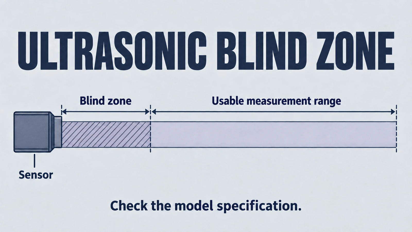
The blind zone is defined as the spatial region immediately in front of the active transducer face where the sensor cannot reliably detect a target. This inability stems from overlapping mechanisms:
- Ring-Down (Residual Vibration): The transducer is still vibrating from the transmission event. This residual mechanical noise masks the weak returning echo from a close target.
- Switching Latency: In monostatic (single-transducer) systems, the electronics must switch from high-voltage transmission mode (Tx) to high-sensitivity reception mode (Rx). During this transition, the receiver is effectively deaf or saturated.
- Near-Field Diffraction: The acoustic near-field (Fresnel zone) is characterized by chaotic constructive and destructive interference, leading to amplitude fluctuations that can confuse amplitude-based detection algorithms.
For industrial automation engineers, the blind zone represents a "keep-out" volume. Any object entering this zone does not merely register as "0 distance"; it often yields unpredictable behavior, such as detecting the sensor's own housing ringing or reporting the maximum range value due to the absence of a discernible echo above the noise floor. Products like the MU18 Ultrasonic Distance Sensor are carefully characterized to define this zone precisely.
2. Electromechanical Transducer Dynamics
To rigorously understand why the blind zone exists, we must analyze the piezoelectric transducer as a damped harmonic oscillator. The fundamental component of most industrial ultrasonic sensors is a lead zirconate titanate (PZT) ceramic element (often PZT discs or PZT rings for larger assemblies), chosen for its high electromechanical coupling coefficient.
2.1 The Harmonic Oscillator Model
The vibration of the piezoelectric element can be described by the classic differential equation for a damped harmonic oscillator. This model connects the electrical input to the mechanical displacement of the sensor face.
Where:
- is the effective mass of the vibrating face (ceramic + matching layer + radiation mass).
- is the mechanical damping coefficient (determined by backing material, internal friction, and air load).
- is the stiffness of the ceramic assembly.
- is the driving force provided by the electrical excitation via the inverse piezoelectric effect.
- is the displacement of the sensor face.
When the electrical drive signal ceases (at ), the system undergoes free vibration (ring-down). The displacement decays exponentially:
Where:
- is the initial amplitude at the end of the pulse.
- is the damping ratio, defined as .
- is the undamped natural frequency.
- is the damped natural frequency, .
Implication for Blind Zone:
For an envelope-threshold receiver, compare the received-voltage envelope with a voltage threshold. Mechanical displacement x(t) requires a defined transduction model and must not be compared directly with voltage; its instantaneous zero crossings do not imply decay. With time measured from the burst start, a simplified overlapping-recovery model uses t_ready = t_burst + max(t_ring, t_recovery, t_switch). Use the actual event timeline when these intervals do not overlap; minimum leading-edge range is approximately c t_ready/2.
The factor of 2 accounts for the round-trip travel of the sound wave. If the ring-down time is 600 s and the speed of sound is 343 m/s:
The 600 μs calculation is a 10.29 cm round-trip-equivalent distance. It represents the whole minimum range only when 600 μs is the total effective blanking time from the chosen transmit origin; if it is post-burst ring-down alone, burst duration and receiver timing must also be included. Compare the actual specification when selecting SR55 or other range sensors.
2.2 The Equivalent Circuit (Butterworth-Van Dyke)
For electrical engineers, it is often more intuitive to view the transducer through the lens of the Butterworth-Van Dyke (BVD) model. This equivalent circuit models the mechanical properties as electrical components:
- (Static Capacitance): Represents the dielectric capacitance between the electrodes.
- (Motional Inductance): Analogous to the mass () of the vibrator.
- (Motional Capacitance): Analogous to the compliance (inverse of stiffness ).
- (Motional Resistance): Analogous to the damping () and acoustic radiation loss.
The "ringing" is the oscillation of energy sloshing between and . The resistor is the element that dissipates this energy. To reduce the blind zone, we must increase the rate of energy dissipation. In circuit terms, we want to lower the Q-factor of this series RLC branch. However, consists of two parts:
- Useful Radiation Resistance (): Energy leaving the sensor as sound.
- Loss Resistance (): Energy lost as heat in the ceramic and mount.
The dilemma is that we want high for range (transmission efficiency) but high total damping for a short blind zone. These requirements often conflict, forcing a trade-off between the maximum detectable range and the minimum detectable distance. High-performance units like the Ultranova1 Ultrasonic Sensor employ advanced matching layers to optimize this balance.
3. The Phenomenon of Ring-Down and Quality Factor
The duration of the ring-down phase is the single most critical variable determining the blind zone. This duration is mathematically governed by the transducer's Quality Factor ().
3.1 Defining Q in Piezoelectric Systems
The Quality Factor () is a dimensionless parameter that characterizes the resonator's bandwidth relative to its center frequency. Its conventional energy definition is 2π times energy stored divided by energy dissipated per cycle, for the specified resonator and loading.
Alternatively, in terms of bandwidth ():
Where is the resonant frequency.
In the context of ultrasonic sensors, dictates the envelope of the ring-down signal. The amplitude decay can be approximated by counting the number of cycles () it takes for the amplitude to drop to a certain fraction (e.g., or half). For an isolated lightly damped linear resonance, the amplitude envelope decays to 1/e in approximately Q/π cycles; stored energy reaches 1/e in approximately Q/(2π) cycles. The sensor blind zone also depends on excitation, receiver recovery, and detection threshold.
3.2 The High-Q vs. Low-Q Trade-off
This parameter introduces a fundamental engineering trade-off that dictates sensor selection:
- High-Q Transducers ():
- Behavior: Like a high-quality tuning fork.
- Advantages: Store energy efficiently. They produce high sound pressure levels (SPL) and are excellent for long-range detection (e.g., 5-10 meters) because the energy is concentrated in a narrow frequency band. Often used in long-range MU30 series sensors.
- Disadvantages: They dissipate energy slowly. Once excited, they continue to vibrate for many cycles. This leads to long ring-down times and large blind zones. They are poor at resolving short pulses.
- Low-Q Transducers ():
- Behavior: Like a thudding drum.
- Advantages: Dissipate energy quickly. They have short ring-down times and small blind zones, making them ideal for short-range precision. They have wider bandwidth, allowing for shorter, sharper pulses.
- Disadvantages: They generate lower output power, reducing maximum range. The energy is spread over a wider spectrum, reducing the peak intensity at the resonant frequency.
Automation engineers must understand that one cannot optimize for maximum range (High Q) without accepting a larger blind zone, unless active damping techniques are employed.
3.3 Piezoelectric Material Selection
The choice of PZT material fundamentally dictates the factor. When browsing the technical specifications on yujiepiezo.com, understanding the material grade is crucial:
- Hard PZT (e.g., PZT-4, PZT-8): Characterized by low dielectric losses and high mechanical (often ). These materials are "hard" to depolarize and "hard" to drive to high amplitudes without heating. We generally recommend these for high-power ultrasonic cleaning and ultrasonic welding applications rather than sensing. Learn more about different geometries like tubes, rectangular plates, and hollow spheres for specific applications in our geometry guide.
- Soft PZT (e.g., PZT-5A, PZT-5H): Characterized by higher compliance, higher piezoelectric constants (), and lower mechanical (typically ). These are "soft" in magnetic analogy. They are preferred for sensing applications such as stainless steel housing ultrasonic sensors because they settle faster, naturally reducing the blind zone. They also offer better sensitivity () for receiving weak echoes.
For custom sensor designs, opting for a Soft PZT formulation is the first step in minimizing the blind zone at the material science level.
4. Scaling Laws and the Miniaturization Paradox
A recurring and counter-intuitive question from automation engineers is: "Why do smaller, compact ultrasonic sensors often struggle with proportionally larger blind zones?" One might expect a tiny M18 sensor to be more agile and settle faster than a massive M30 sensor. However, the physics of acoustic radiation dictates the opposite.
4.1 Radiation Impedance and the Piston Model
To understand this, we must look at Radiation Impedance. A sensor face vibrating in air can be modeled as a circular piston in a baffle. The efficiency with which this piston transfers energy into the air depends on the ratio of its size to the wavelength of sound ().
For an ideal uniformly moving circular piston in an infinite rigid baffle, the mechanical radiation resistance is the force/velocity quantity. Its small-ka approximation scales as frequency squared times radius to the fourth for fixed fluid density and sound speed; ka must be much smaller than one. Acoustic pressure/volume-velocity or specific-impedance conventions use different area factors. This scaling is not an assembled sensor’s ring-down prediction.
Where is the wavenumber () and is the radius of the sensor.
The Paradox:
- Large Sensors (High ): When the sensor is large relative to the wavelength, it couples efficiently to the air. The air acts as a significant load, absorbing energy from the sensor. This "radiation damping" helps stop the sensor from ringing.
- Small Sensors (Low ka): The piston model predicts lower radiated power for a fixed face velocity at small ka. Residual decay depends on stored modal energy and all loss/load paths, including backing, mounting and electronics; miniaturization alone does not establish a longer ring-down or reliance solely on internal friction.
4.2 PMUTs and the High-Q Trap
As sensors are miniaturized using MEMS technology (Piezoelectric Micromachined Ultrasonic Transducers - PMUTs), the active element changes from a bulk ceramic block to a thin suspended membrane.
- Reduced Bandwidth: PMUTs typically exhibit lower bandwidth and higher Quality Factors () compared to bulk piezoelectric transducers.
- Extended Ring-Down: For the same loaded mode and threshold, decay time scales with Q/f. PMUT and bulk-transducer comparisons require identified devices, medium, frequency, loading and decay criterion; generic 10–20 versus 50–100 cycle ranges do not establish an architecture-wide rule.
- Proportionality: If a micro-sensor has a diameter of 3mm but a ring-down distance of 150mm, the blind zone is 50x the sensor diameter. Contrast this with a 30mm industrial sensor having a 300mm blind zone (10x diameter). The miniaturized sensor is significantly less efficient at stopping its own vibration relative to its size.
4.3 Housing Resonance (Acoustic Short Circuit)
In compact M12 or M18 housings, there is very little physical mass available to dampen the vibration of the ceramic element.
- Structure-Borne Noise: The vibration from the piezo element can couple into the sensor housing (barrel). If the housing itself begins to ring at the resonant frequency, it acts as a secondary source of vibration.
- Feedback Loop: The sensitive receiver circuitry, also mounted within this vibrating housing, detects this structure-borne noise as a false echo. This creates a "near-field blind zone" that persists as long as the housing vibrates, often far longer than the ceramic element itself.
5. Signal Processing Limitations and Time-of-Flight
The blind zone is not only a mechanical phenomenon but also a signal processing constraint related to the Time-of-Flight (ToF) measurement principle and the limitations of the receiver electronics.
5.1 The Round-Trip Constraint
The core formula for ultrasonic distance calculation is:
Where is the speed of sound (~343 m/s at 20°C). To measure a target at a very short distance, say 10 mm (0.01 m), the total round-trip time is:
This implies the sensor system must complete the following sequence within 58 microseconds:
- Transmission: Emit the pulse train.
- Settling: Stop vibrating completely (or below threshold).
- Switching: Switch electronics from Tx (100V+) to Rx (micro-volt sensitivity).
- Detection: Identify the leading edge of the echo.
5.2 Pulse Width Limitations
A typical ultrasonic burst consists of 8 to 16 cycles of the carrier frequency to excite the high-Q ceramic. At a standard frequency of 40 kHz, the period is .
- Pulse Duration: 8 cycles 25 = 200 .
- Physical Length of Pulse: .
Insight: For a receiver disabled throughout an eight-cycle 40 kHz burst, the 200 μs transmission gives an approximately 6.86 cm spatial pulse length in air and a 3.43 cm leading-edge masking estimate. This bound depends on that gated architecture. Overlapping transmission and reception are not universally impossible; cancellation or simultaneous-reception designs require separate validation.
5.3 Saturation and Recovery Time
In monostatic sensors, the same ceramic element is used for Tx and Rx. High-voltage transformers (step-up) are often used to drive the piezo at 100V-400V to maximize sound pressure. The receiver circuitry, designed to detect microvolts, is physically connected to this high-voltage line.
- Protection Circuits: Diodes or limiting circuits clamp the receiver input during transmission to prevent destruction of the pre-amplifier.
- Recovery Time: Receiver clamps and amplifiers take a finite time to recover. A 500 μs interval corresponds to about 8.575 cm of round-trip-equivalent air range, but is not automatically additive to concurrent mechanical ring-down. Measure the total readiness timeline from the chosen transmission origin.
5.4 Envelope Detection and Thresholding
The receiver does not detect the raw sine wave; it typically rectifies and filters the signal to create an envelope.
- Time-Varying Threshold (TVT): To combat the ring-down noise, engineers use a Time-Varying Threshold. Immediately after transmission, the detection threshold is set very high to ignore the ringing. It decays exponentially over time to increase sensitivity for distant targets.
- The Masking Effect: The high initial threshold in the TVT curve effectively "blinds" the sensor to small targets close to the face. If a small target's echo is weaker than the ring-down noise (and thus lower than the TVT setting), it is ignored. This is why the blind zone is often larger for small targets (like a wire) than for large targets (like a flat plate).
6. Frequency, Damping, and Scaling Laws
The operating frequency of the sensor is the primary lever engineers have to manipulate the blind zone. However, this lever comes with significant consequences for range and attenuation.
6.1 Frequency Scaling Relationships
There is an inverse relationship between frequency and blind zone size. Higher frequencies imply shorter wavelengths and shorter periods. Specialized sensors, such as those used for precision measurements (Ultranova2), optimize this balance meticulously.
| Frequency | Typical Application | Wave Period (T) | Pulse Length (10 cycles) | Est. Blind Zone |
|---|---|---|---|---|
| 40 kHz | Parking sensors, tank levels | 25 s | ~8.6 cm | 200 mm - 500 mm |
| 125 kHz | Industrial automation | 8 s | ~2.7 cm | 50 mm - 150 mm |
| 300 kHz | Label detection, bottle fill | 3.3 s | ~1.1 cm | 15 mm - 50 mm |
| 1 MHz | Medical, NDT, thickness | 1 s | ~0.3 cm | < 5 mm |
Analysis: Ten cycles last 25 μs at 400 kHz and 250 μs at 40 kHz. Those correct burst/decay examples do not determine complete sensor blind range. Higher frequency generally increases air absorption, but molecular relaxation and environment prevent a universal f² law across all conditions. Usable range depends on transducer, drive, target and atmosphere; 400 kHz does not impose a universal maximum below one metre.
6.2 Mechanical Damping Strategies
To reduce ring-down without changing frequency, manufacturers employ mechanical damping.
- Backing Material: A highly absorptive material (usually epoxy mixed with tungsten powder or rubber) is bonded to the rear of the piezo crystal. This material is designed to have an acoustic impedance () that matches the ceramic. This allows the backward-traveling wave to enter the backing material where it is absorbed, rather than reflecting back and forth in the crystal. This adds mechanical resistance (), forcing the vibration to decay faster.
- Damping Trade-off: Heavy damping reduces the factor. While this shortens the blind zone, it also reduces the output amplitude (transmission power) and receiver sensitivity. A heavily damped sensor has a "dead" feel—excellent for close range, but poor for detecting small or distant targets.
6.3 Active Electronic Damping
Advanced industrial sensors (like those discussed regarding the SR55 or SR80 Ultrasonic Sensor) may employ active damping.
- Technique: Immediately after the excitation pulse, the drive circuit applies a short burst of signal that is 180° out-of-phase with the residual vibration.
- Effect: This "counter-pulse" or "braking pulse" actively cancels the mechanical momentum of the ceramic, forcing it to a standstill much faster than natural exponential decay.
- Result: Active damping can reduce residual vibration in a validated design. Report improvement against an identified baseline, decay threshold and complete sensor configuration; a universal percentage is not established.
7. Topology: Monostatic vs. Bistatic
The choice of transducer topology is the architectural decision that determines whether a ring-down blind zone exists at all.
7.1 Monostatic (Transceiver)
- Configuration: One transducer handles both Tx and Rx.
- Pros: Lower cost, smaller footprint, single acoustic path (no parallax), simpler cabling.
- Cons: Inescapable blind zone due to ring-down and switching. The receiver is blind while the transmitter is active and settling.
- Architecture: Monostatic designs use one element for transmission and reception. Confirm the selected model’s architecture rather than inferring it from an unsupported market-share figure.
7.2 Bistatic (Separate Transmitter & Receiver)
- Configuration: One transducer transmits; a physically separate transducer receives. They are often housed in the same block but acoustically isolated.
- Physics: A separate receiver avoids its own high-voltage transmit excitation, but remains resonant and can respond to direct acoustic or structural coupling. Isolation, recovery, beam overlap and the separate transmit/receive path lengths still require validation.
- Implication: Bistatic sensors theoretically exhibit zero ring-down blind zone. They can detect objects almost touching the sensor face.
- The Hidden Limitation (Geometric Blind Zone): While they have no temporal blind zone, they have a geometric blind zone. Due to the separation distance between Tx and Rx, the transmitted beam and the receiver's field of view may not overlap until a few centimeters in front of the unit. This "triangulation gap" creates a zone where the echo does not hit the receiver.
- Crosstalk: Additionally, "crosstalk" (direct sound leakage from Tx to Rx through the housing material) can simulate a blind zone. If the isolation material between the two heads is insufficient, the receiver hears the transmitter directly through the sensor body, masking real echoes. Specialized sensors like the MDC Double Sheet Detection Sensor often utilize separate transmitters and receivers to manage these issues.
8. Environmental and Operational Variables
The blind zone is not a fixed value; it "breathes" with the environment. Engineers must account for these variations to avoid intermittent failures.
8.1 Temperature Effects
The blind zone distance is calculated based on the speed of sound ().
The speed of sound in dry air is approximated by:
- Cold Environment (-20°C): . Sound travels slower. For a fixed ring-down time , the physical blind zone distance decreases.
- Hot Environment (+60°C): . Sound travels faster. The physical blind zone expands.
Implication: A sensor calibrated with a static blanking distance at room temperature might fail in a hot environment because the ring-down noise now extends physically further into the detection zone.
8.2 Humidity and Pressure
- Humidity: Attenuation may increase or decrease over the operating range depending on frequency, temperature, pressure and humidity. Calculate or measure under specified conditions; echo margin and the detection algorithm determine any resulting change in usable range.
- Pressure: Changes in atmospheric pressure (e.g., high altitude) affect the acoustic impedance of the air (). Lower pressure reduces the air's density (), lowering the acoustic load on the sensor. As discussed in Section 4.1, reduced loading leads to less radiation damping, potentially increasing the ring-down time and extending the blind zone.
8.3 Tank Reflections (Multipath)
In tank level applications, side-wall reflections can be mistaken for ring-down noise.
- Beam Spread: Ultrasonic sensors have a conical beam (typically 7-15°). If the sensor is mounted too close to a tank wall, the edge of the beam hits the wall.
- Reverberation: In the near field, these reflections can bounce back and forth between the sensor face and the wall. This reverberation merges with the transducer ring-down, extending the effective blind zone far beyond the sensor's datasheet specification. This is often misdiagnosed as a "long blind zone" when it is actually an installation error. Robust product solutions like the SF2 Ultrasonic Sensor are designed to minimize side-lobe effects in tank applications.
9. Mechanical Integration and Installation Mistakes
Even with a perfectly specified sensor, the blind zone can be artificially extended by improper integration. The mechanical interface between the sensor and the machine is a critical part of the acoustic system.
9.1 The Mounting Torque Trap
A frequent cause of "extended blind zones" in the field is over-torquing the mounting nuts on threaded cylindrical sensors.
- Mechanism: Ultrasonic sensors are precision instruments containing piezoelectric ceramics and damping materials. Squeezing the sensor barrel with excessive force deforms the housing. This deformation can compress the internal acoustic isolation materials (foams or elastomers) that separate the vibrating head from the static body.
- Acoustic Short Circuit: Once the isolation is compromised, the vibration from the head couples directly into the housing barrel. The entire sensor body begins to ring. This structure-borne ringing typically has a lower frequency and longer decay time than the ceramic itself.
- Result: Undesired housing coupling may cause false echoes or reduce usable near-range performance. Its frequency, decay and magnitude are design-dependent; verify the actual installation rather than assuming a fixed expansion from 20 to 50 cm.
- Fix: Follow the exact sensor maker’s prescribed mounting hardware, contact points, maximum torque and isolation method. Do not infer torque from M18/M30 thread size or add generic washers unless the model’s installation procedure specifies them.
9.2 Acoustic Crosstalk in Arrays
When multiple sensors are mounted close together (e.g., on a robotic arm or conveyor), they can blind each other.
- Direct Interference: The pulse from Sensor A is heard by Sensor B. If Sensor B is in its listening window, it registers this as a target.
- Synchronization: To prevent this, sensors must be synchronized (fired simultaneously) or multiplexed (fired sequentially). Without this, the random interference creates a noise floor that forces the engineer to increase the threshold voltage, which in turn reduces sensitivity and increases the effective blind zone for small targets.
10. Analyzing Datasheets: Reading Between the Lines
When selecting sensors from the Ultrasonic Sensors hub at yujiepiezo.com, engineers must decode specific parameters to evaluate blind zone performance.
10.1 "Operating Range" vs. "Limit Range"
Datasheets often list two ranges:
- Operating Range (Scanning Range): The range where detection is documented for standard targets with operating reserve.
- Blind Zone (Dead Band): Explicitly stated as the minimum distance (e.g., "0...200 mm undefined").
Critical Note: In the blind zone, the output state is undefined. It might hold the last known value, switch to zero, or toggle rapidly between max and min. Advanced sensors allow you to program the "behavior" in the blind zone (e.g., force output to "Full" or "Empty" for safety), but they cannot measure there. Consider options like the MRR1 Ultrasonic Sensor for precise short-range applications.
10.2 Response Curves and Lobes
Look for the "Detection Zone" diagrams (lobes).
- Axial Blind Zone: The gap at the origin of the X-axis.
- Lateral Blind Zone: Note that close to the sensor face, the beam may be narrower than the transducer diameter, creating blind spots around the periphery of the sensor face. The "near field" is not a uniform cone; it often narrows before spreading out.
| Sensor Size | Typical Max Range | Typical Blind Zone | Blind Zone Ratio (%) |
|---|---|---|---|
| M12 (Miniature) | 1200 mm | 100 mm | ~8.3% |
| M18 (Standard) | 2000 mm | 200 mm | ~10% |
| M30 (Long Range) | 6000 mm | 600 mm | ~10% |
Blind distance and maximum range are separately specified for the complete model and target conditions. A universal 5–10% ratio is not established by housing size or frequency; use measured performance throughout the required window.
11. Mitigation Strategies and Conclusion
The ultrasonic blind zone is an immutable physical characteristic derived from the inertia of the piezoelectric element and the finite length of the acoustic pulse. It is not a defect, but a boundary condition of the technology.
11.1 Engineering Workarounds
Since the physics cannot be cheated, the application must be adapted:
- Mechanical Standoffs: Mount the sensor inside a "stilling pipe" or nozzle that physically sets the sensor back from the maximum fill level. The length of the pipe must exceed the blind zone. Caution: The pipe must be smooth and of sufficient diameter to avoid side-wall reflections.
- Deflectors: Use a smooth metal plate at a 45° angle to look "around a corner." The total flight path (Sensor -> Reflector -> Target) is what matters. This effectively folds the blind zone out of the way.
- Use Bistatic Sensors: If the application requires measuring from 0mm to 100mm, a single-head ultrasonic sensor is the wrong tool. Use a thru-beam or retroreflective ultrasonic pair, or switch to an optical sensor.
11.2 Conclusion
For the automation engineer, success lies not in eliminating the blind zone, but in strictly adhering to the "Keep-Out" volume it dictates.
Physics is Absolute: Ring-down is caused by stored mechanical energy (). It cannot be calibrated away; it must be damped or waited out.
Frequency is the Dial: To reduce the blind zone, increase the frequency (select 200-400kHz models). This sacrifices range but tightens the time domain.
Integration is Critical: Prevent housing resonance and acoustic short circuits by respecting torque limits and using isolation mounting.
By understanding the deep physics of the piezoelectric harmonic oscillator, engineers can interpret datasheets more accurately, select the correct PZT materials from suppliers like Yujie Piezo, and design robust automation systems that function reliably within the limits of acoustic science.
Engineering decision notes
Piezo ring and stack design
Use this article when a project depends on annular PZT geometry, preload control, and stable resonance in cleaning or welding stacks. For "Blind Zone Explained: The Hidden Limitation of Short-Range Ultrasonic Sensors", the practical value is in turning the topic into a measurable selection or sourcing decision.
YJ Piezo evaluates ring ceramics by geometry, capacitance band, impedance trend, and stack fit instead of treating diameter and frequency as isolated catalog fields.
Selection checks
- Confirm outer diameter, inner diameter, thickness, and preload method before comparing frequency numbers.
- Match the ceramic ring to the horn, backing mass, and target operating load rather than to the bare ceramic resonance alone.
- Ask for impedance and capacitance records from the same production batch when the stack will run continuously.
Failure risks
- A ring that looks correct on a datasheet can drift after clamping if the stack stress is not controlled.
- Low impedance is useful only when heat, bonding, and drive limits remain inside the safe operating window.
- Using a cleaning ring in a welding stack without validation can create cracking, output loss, or unstable resonance.
RFQ details
- What is the target stack frequency under preload?
- What horn, backing mass, and bolt arrangement will the ring support?
- Do you need outgoing impedance curves, capacitance range, or sample-to-sample spread data?
Relevant YJ Piezo pages
- Piezoelectric Ring Series
Ring dimensions and frequency options for high-power assemblies
- Ultrasonic Welding Transducers
High-power stacks where preload and Qm matter
- Ultrasonic Cleaning Transducers
Cleaning tank applications using ring or disc ceramics
Application FAQ
- When should an OEM choose a piezo ring instead of a disc?
- Choose a ring when the mechanical stack needs a central bolt, defined preload, or higher power transfer through a Langevin-style assembly. Use a disc when the design is lower power, thinner, or does not require a through-hole stack structure.
- What proof should I ask for before approving a custom ring?
- Ask for geometry tolerances, capacitance range, impedance or resonance data, electrode details, and sample spread from the same batch. For high-power use, confirm how the ring behaves after clamping, not just as a loose ceramic.