
Common Failure Modes in Spherically Curved Piezo Ceramics: What Engineers Should Watch for During Design and Procurement
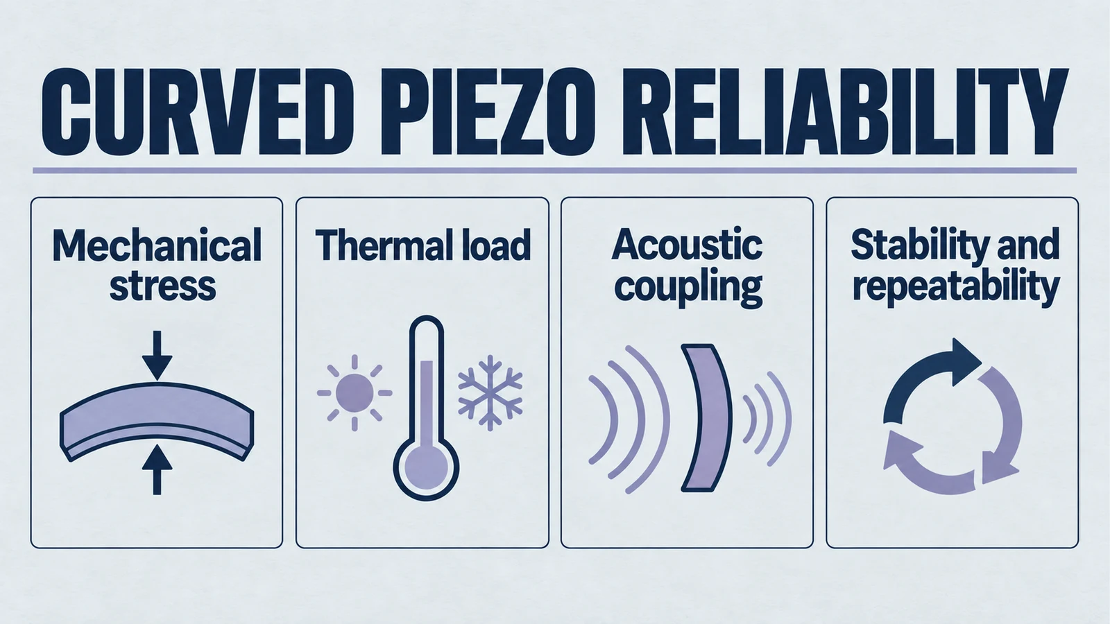
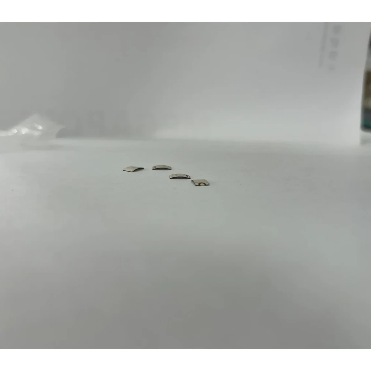
Spherically curved piezo ceramics are often selected when an ultrasonic system requires higher acoustic intensity, tighter beam concentration, or a defined focal region within a compact package. In principle, the concept looks straightforward. Shape the active ceramic into a curved geometry, align the acoustic design with the intended focal distance, and integrate it into the transducer stack. In practice, however, focused piezo ceramics tend to fail in ways that flat elements do not. For a geometry baseline, see this practical introduction to spherically curved piezoelectric ceramics.
The reason is not that curved ceramics are inherently unreliable. The reason is that curvature changes the mechanical stress field, assembly sensitivity, thermal behavior, and long-term polarization stability of the active element. A design that appears acceptable in short bench testing can still develop cracking, drift, loss of output, or early-life instability once real operating conditions, environmental cycling, and lifetime exposure begin to accumulate.
For OEM engineers, reliability engineers, and technical buyers, the key question is therefore not simply whether a curved piezo element can be manufactured. The real question is whether the chosen geometry, material, assembly method, and operating envelope create hidden failure paths that only become visible after qualification, field use, or environmental stress.
This article reviews the most common focused piezo ceramic failure modes and explains how they relate to design choices, operating conditions, and qualification gaps. The goal is not to assign blame to the user or the supplier. Reliability problems in focused ceramics are usually the result of coupled physics. Stress, temperature, polarization state, bonding conditions, and acoustic loading interact in ways that are easy to underestimate during early development.
Product path for this search intent
Match the article topic to the right YJ Piezo product page
Use this article when curved ceramic geometry, focal distance, acoustic intensity, and assembly tolerances matter more than a flat element comparison. For "Common Failure Modes in Spherically Curved Piezo Ceramics: What Engineers Should Watch...", the practical value is in turning the topic into a measurable selection or sourcing decision.
- Spherical Cap Piezoelectric Ceramics
Focused ceramic shapes for OEM ultrasonic assemblies
- Piezoelectric Ceramics
Shape and material options for custom design
- Air Acoustic Transducers
Acoustic interface references for beam behavior
Why Curved Piezo Ceramics Fail Differently From Flat Elements
A flat piezo ceramic already operates under electromechanical stress, but a spherically curved element adds geometric complexity before the transducer is even energized. The forming process, the thickness distribution, the local bending state, and the way the ceramic interfaces with backing, matching layers, housings, or adhesives all influence where stress accumulates and how the part ages. This is why teams usually review radius, aperture, and thickness interactions early.
Curvature also tends to reduce tolerance forgiveness. A small geometric deviation, a local bonding void, a support-ring mismatch, or a slight thermal gradient may be survivable in a flat element but become critical in a curved one because the stress distribution is already non-uniform. In other words, focused piezo ceramic failure modes are rarely random. They usually follow the geometry.
That is why focused piezo ceramic failure modes should be evaluated as a system-level reliability issue rather than as a simple material defect question. Integration path choices in focused transducer architecture can amplify or reduce these risks.
Mechanical Cracking and Stress Concentration Patterns
Mechanical cracking is one of the most visible and costly failure modes in spherically curved piezo ceramics. Yet the crack itself is usually the final symptom, not the original cause.
In a curved ceramic, stress does not distribute evenly across the surface. Local tensile concentrations can form near the rim, around the transition zone between free and constrained regions, near electrode discontinuities, or wherever the ceramic is forced into imperfect contact with a mating structure. If the support structure, adhesive layer, or mounting profile does not match the real geometry of the ceramic, the part may experience preload conditions that are already close to its mechanical tolerance before electrical drive is applied.
Once the transducer is running, dynamic stress adds another layer. Repeated vibration cycles can amplify existing concentration points. Even when the ceramic survives initial electrical testing, microcracks can start at locations where the combination of curvature, clamping, and vibration creates cyclic tensile loading. These cracks may first appear as a slight impedance shift, intermittent output instability, or a subtle decrease in acoustic consistency rather than a dramatic fracture. For related dynamics, review mode coupling risk in piezo ceramics.
Several cracking patterns are especially relevant in focused ceramics:
- Edge-initiated cracking. The perimeter often carries elevated stress because it is the region most affected by assembly mismatch, adhesive shrinkage, support constraints, and thickness variation.
- Radial crack propagation. Once a crack starts near a high-stress region, it may propagate inward along stress paths shaped by the spherical geometry.
- Local cracking around bonded interfaces. Hard adhesive spots, partial wetting, or uneven curing can create rigid islands that concentrate stress under vibration and thermal cycling.
- Delayed cracking after environmental exposure. A part may survive factory acceptance tests, then fail after temperature cycling, humidity exposure, or repeated start-stop operation because those conditions reveal latent stress concentrations that were not obvious at room temperature.
When engineers ask about piezo ceramic cracking causes, the answer is often not a single overload event. More often it is an accumulation problem. The ceramic is asked to operate in a geometry and assembly state that leaves too little margin for process variation and real-life duty.
Depoling and Performance Drift Under Sustained Load
A second major failure mode is depoling, or partial loss of polarization, which leads to reduced sensitivity, lower output, changing resonance behavior, and unstable long-term performance.
Depoling in curved ceramics is particularly important because these components are often used in focused ultrasonic systems where output density matters. A modest drop in electromechanical performance may not look severe on paper, but it can materially change focal intensity, signal response, or process consistency in the final system.
Depoling is usually driven by a combination of elevated electric field, temperature, mechanical stress, and time. None of these factors acts in isolation. A design may appear stable during short validation bursts, yet gradually drift under sustained duty because the ceramic is being operated too close to its polarization retention limits. Teams working on focused piezo driving challenges often see this only after long-run trending.
Curved geometries can intensify this issue in several ways. First, local stress states are less uniform than in flat ceramics, so some regions may depole faster than others. Second, focal intensity describes energy in the target medium; it does not by itself establish internal ceramic heating. Determine dielectric, mechanical and interface dissipation, loading and thermal paths separately. Third, if the ceramic is part of an assembly with imperfect thermal dissipation, temperature rise can remain localized and invisible until measurable drift has already developed.
The early signs of depoling and drift are often misread. Engineers may see reduced amplitude and assume drive electronics variation, coupling inconsistency, or instrumentation error. In reality, the ceramic may be experiencing gradual internal degradation. This is why ultrasonic transducer reliability issues often emerge first as trend changes rather than as hard failures.
Common indicators include:
- Reduced capacitance or a shift in impedance signature.
- Lower acoustic output at the same drive condition.
- Changes in resonance or anti-resonance behavior over time.
- Increased variability between repeated runs after thermal soak.
- A component that still functions, but no longer meets the original focal or output target.
A key reliability lesson is that pass-fail thinking is too crude here. A focused piezo ceramic can remain electrically alive while becoming functionally unreliable.
Thermal Runaway Scenarios and Early-Life Failures
Thermal problems are among the most underestimated risks in focused ceramics. Designers often evaluate nominal temperature rise under controlled conditions and conclude that the part is operating safely. But real failure behavior is often nonlinear.
Thermal runaway begins when internal losses and insufficient heat removal reinforce each other. As the element heats up, material properties shift. Electrical losses may increase. Mechanical damping changes. Acoustic loading can move away from the originally assumed state. The transducer then requires more drive to maintain performance, which produces more heating, which pushes the part even further from its stable operating point.
Focused ceramics can be vulnerable because the very purpose of the geometry is to concentrate energy. If the system is acoustically mismatched, poorly cooled, intermittently unloaded, or driven beyond the realistic duty cycle, the element may develop hot spots that do not appear in simplified average-temperature measurements. Conservative screening from continuous-duty piezo selection practice is useful here.
Early-life failures often happen when latent weaknesses meet this thermal stress quickly. For example, a ceramic with a small forming-induced flaw, a locally stiff adhesive region, or a non-uniform electrode area may survive incoming inspection and short functional tests. But after repeated high-duty bursts, the local temperature field can become uneven enough to trigger cracking, depoling, adhesive degradation, or rapid drift. The failure then looks premature, even though the part was actually operating with too little thermal margin from the start.
Thermal runaway risk is especially high when one or more of the following conditions are present:
- The duty cycle used in real operation is higher than the qualification profile.
- Acoustic coupling conditions vary in the field more than they did in the lab.
- The system depends on intermittent cooling assumptions that are not always met.
- Backing or housing design removes heat less effectively than expected.
- Electrical tuning changes during warm-up, increasing loss rather than reducing it.
A practical mistake is to assume that a component which survives a short power test is thermally robust. That conclusion is often far too optimistic.
Why Some Failures Only Appear After Environmental or Lifetime Testing
One of the most frustrating aspects of focused ceramic qualification is that many weak designs pass initial inspection, pass room-temperature electrical checks, and even pass short acoustic tests. The real problems emerge only after environmental conditioning or lifetime cycling.
This happens because several critical damage mechanisms are progressive. They require time, repetition, or environmental variation to become visible.
Temperature cycling can reveal mismatch in thermal expansion between the ceramic and bonded structures. Humidity exposure can alter adhesive properties, interface stability, or insulation robustness. Repeated power cycling can expose growing drift in resonance behavior. Mechanical vibration and start-stop operation can turn microscopic flaws into measurable performance loss. None of these effects needs to be dramatic in a single cycle. The danger lies in accumulation.
Lifetime testing is therefore not just a formality. It is often the first stage at which the real interaction between geometry, polarization stability, thermal behavior, and assembly design becomes measurable. Engineers who skip or shorten this stage may incorrectly conclude that the design is mature, when in fact they have only confirmed that the part can survive demonstration conditions. For test planning depth, compare repeatable piezo measurement workflows and integration failure patterns in OEM systems.
This also explains why procurement specifications that focus only on dimensions, capacitance, and room-temperature resonance data are incomplete. Those parameters are necessary, but they do not reveal whether the part will remain stable after environmental exposure or extended energized use.
Failure Modes That Are Often Misdiagnosed
In practice, several reliability problems in curved ceramics are misdiagnosed because the visible symptom appears in a different subsystem.
- A falling output level may be attributed to poor acoustic coupling, even though the real cause is gradual depoling.
- An unstable frequency response may be blamed on electronics drift, even though local cracking or interface degradation has shifted the mechanical behavior of the element.
- Intermittent performance spread between units may be labeled as supplier inconsistency, even though the deeper issue is that the design has insufficient tolerance margin and small normal variations are being amplified by the curved geometry.
- An early fracture may be described as shipping damage, even though the root problem was pre-existing stress concentration that only needed one additional thermal or mechanical event to become visible.
These distinctions matter because corrective action depends on root mechanism. If the failure is driven by system physics, merely tightening one inspection item will not solve it.
Design and Procurement Factors That Influence Reliability
Reliability begins long before field operation. In focused ceramics, design and procurement decisions strongly shape the final risk profile.
The most important factors include the relationship between curvature radius, aperture, and thickness. An aggressive geometry may improve focusing but reduce manufacturability margin and increase local stress sensitivity. Engineers evaluating curvature choices can cross-check with radius-of-curvature selection guidance.
Material selection matters as well. A formulation that performs well in one frequency and duty range may not hold polarization equally well in another thermal or mechanical environment. Source options for focused elements are often compared across custom spherical-cap piezo ceramics, broader piezoelectric ceramic categories, and geometry alternatives like disc, ring, and tube elements.
Support conditions are equally critical. Whether the ceramic is edge-supported, partially bonded, fully backed, or integrated into a multilayer stack will change both stress distribution and heat flow.
Drive conditions should also be specified realistically. Peak voltage, sustained duty, startup transients, no-load or partial-load scenarios, and environmental temperature range all affect the failure envelope. Electrical risk should be reviewed with the same discipline used in driver electronics integration.
For technical buyers, the risk is not only selecting the wrong supplier. It is also issuing a procurement package that is too shallow to expose meaningful reliability differences. If the specification only asks for nominal dimensions and initial electrical data, many latent failure risks will remain hidden until integration.
A Practical Reliability Checklist for Focused Piezo Ceramics
When evaluating a focused ceramic design or supplier capability, engineers should ask reliability questions that reflect real operating physics.
- Is the assembly likely to create rim loading, local constraint, or adhesive-induced stress concentration?
- Have the drive voltage, duty cycle, and acoustic loading conditions been defined using realistic use cases rather than ideal lab assumptions?
- Has the design been checked for localized heating rather than only average temperature rise?
- Is performance stability monitored over time, or is validation limited to initial pass-fail measurements?
- Have temperature cycling, humidity exposure, and lifetime cycling been included in qualification?
- Are impedance, capacitance, output, and resonance behavior trended before and after stress testing?
- Does the geometry leave enough tolerance margin for variation in forming, bonding, and assembly alignment?
- Has the system been tested in off-nominal conditions such as partial coupling, thermal soak, repeated startup, or sustained operation near the upper duty limit?
These questions do not by themselves confirm success, but they sharply improve the odds of identifying risk before field deployment. Early feasibility checks from when not to use focused ceramics can also prevent misaligned design commitments.
Conclusion
Spherically curved piezo ceramics can enable highly effective focused ultrasonic designs, but they also introduce reliability risks that are easy to underestimate during early development. The most common problems, including mechanical cracking, depoling, performance drift, thermal runaway, and delayed failures after environmental or lifetime exposure, are not isolated events. They are usually the visible result of how geometry, stress, temperature, polarization, and assembly conditions interact over time.
That is why reliability evaluation of focused ceramics should never be reduced to a dimension check or a brief functional test. Engineers need to examine how the part behaves under realistic thermal, mechanical, and acoustic conditions, especially where curvature reduces tolerance forgiveness.
For procurement teams and OEM developers alike, the most useful mindset is not to ask whether a curved ceramic works on day one. The better question is whether the design still has enough margin after thermal cycling, sustained load, environmental exposure, and normal manufacturing variation have all taken their turn. That is where real qualification begins. If you need project-specific support, use the engineering contact channel.
Related Technical Reading
Focused geometry and failure mechanisms
- Spherically curved piezoelectric ceramics: practical introduction
- Key design parameters: radius, aperture, thickness
- How to choose radius of curvature for focused ceramics
- Mode coupling and geometry-driven risk
- Focused piezo ceramics in constrained medical environments
Validation and integration reliability
- Electrical driving challenges of focused piezo ceramics
- Common integration mistakes in OEM ultrasonic systems
- Selecting piezo ceramics for continuous-duty applications
- How to test and measure piezoelectric materials
Products and sourcing paths
Engineering decision notes
Focused and curved piezo ceramics
Use this article when curved ceramic geometry, focal distance, acoustic intensity, and assembly tolerances matter more than a flat element comparison. For "Common Failure Modes in Spherically Curved Piezo Ceramics: What Engineers Should Watch...", the practical value is in turning the topic into a measurable selection or sourcing decision.
YJ Piezo reviews curved ceramics as geometry-sensitive acoustic components, where aperture, curvature, thickness, electrode layout, and mounting boundary all affect the usable focus.
Selection checks
- Define focal distance, aperture, medium, and allowable package depth before selecting curvature.
- Review resonance behavior with the intended mounting boundary, not only as a loose ceramic.
- Plan sample validation around beam behavior, impedance spread, and thermal drift.
Failure risks
- A curved part can meet dimensional drawings but miss the intended acoustic focus if the boundary condition changes.
- Mode coupling can create unstable frequency behavior after assembly or thermal loading.
- Over-optimizing peak intensity can reduce practical tolerance to alignment and field conditions.
RFQ details
- What focal distance, aperture, and working medium are required?
- Is the ceramic bonded, clamped, housed, or used as a bare focused element?
- Do you need impedance spread, acoustic validation, or geometry tolerance records?
Relevant YJ Piezo pages
- Spherical Cap Piezoelectric Ceramics
Focused ceramic shapes for OEM ultrasonic assemblies
- Piezoelectric Ceramics
Shape and material options for custom design
- Air Acoustic Transducers
Acoustic interface references for beam behavior
Application FAQ
- Why are curved piezo ceramics harder to specify than flat ceramics?
- Curvature changes the acoustic field and can interact with mounting, bonding, and drive conditions. The useful specification must include geometry, focus, medium, resonance behavior, and assembly boundary.
- What should be validated before buying focused piezo ceramics in volume?
- Validate focal distance, impedance spread, frequency stability after assembly, thermal behavior, and the tolerance stack between ceramic geometry and the final housing.