
Focused Piezo Ceramics for Medical Ultrasound: Engineering Constraints That Determine Whether a Design Is Viable
Focused Piezo Ceramics for Medical Ultrasound: Engineering Constraints That Determine Whether a Design Is Viable
Medical ultrasound teams often reach for spherically curved (focused) piezoelectric ceramics because focusing looks like “free gain.” A smaller focal spot can increase intensity at depth. A curved element can simplify an acoustic stack. A prototype can look great on day one.
Then reality arrives. Tissue loading varies. Coupling changes between operators and end users. Heat accumulates in places your early benchtop test never revealed. After hours, not minutes, the same transducer begins to drift. A bond line slowly weakens. A cable or solder joint fails first. A once-clean focal profile becomes unpredictable.
This article is a feasibility and risk-assessment guide for engineers evaluating focused piezo ceramics medical ultrasound designs. It is written for decisions that must be defensible before you commit to prototyping, supplier tooling, or procurement.
Product path for this search intent
Match the article topic to the right YJ Piezo product page
Use this article when curved ceramic geometry, focal distance, acoustic intensity, and assembly tolerances matter more than a flat element comparison. For "Focused Piezo Ceramics for Medical Ultrasound: Engineering Constraints That Determine W...", the practical value is in turning the topic into a measurable selection or sourcing decision.
- Spherical Cap Piezoelectric Ceramics
Focused ceramic shapes for OEM ultrasonic assemblies
- Piezoelectric Ceramics
Shape and material options for custom design
- Air Acoustic Transducers
Acoustic interface references for beam behavior
It is not an application overview. It is not finished-device guidance. It is not regulatory advice. It is an engineering constraint map.
What “focused ceramic” actually buys you. And what it does not
A spherically curved piezo element provides geometric focusing. In ideal conditions, it can increase on-axis pressure at a target depth relative to a comparable unfocused radiator. To understand the geometry background, see spherical cap vs hemispherical piezo ceramics and this practical explainer on how bowl-shaped piezo ceramics focus ultrasound.
But focusing does not automatically solve:
- Acoustic coupling variability. The focal gain you measure in a tank can evaporate when coupling is inconsistent.
- Thermal budget. Focusing concentrates acoustic power. It also concentrates loss mechanisms.
- Stability requirements. Medical systems often require repeatable behavior over long sessions and across many uses.
Before you choose a focused ceramic, you need to know if the design is viable under:
- your power density and duty cycle,
- your loading and coupling variability,
- your long-term stability expectations,
- and your failure tolerance.
A useful mental model: focusing is a constraint amplifier. Anything that is marginal in a flat element tends to become more sensitive in a focused element. That includes temperature margins, bond integrity, coupling, and dimensional tolerances. This is why many teams eventually ask when not to use focused piezoelectric ceramics.
Decision first. Is your application in the “focused ceramics viable” zone
A focused element is most defensible when:
- The application truly benefits from localized intensity at a specific depth range.
- The system can maintain controlled coupling conditions.
- The acoustic stack can reject or manage heat such that temperature rise is bounded.
- Performance targets tolerate some drift, or the system includes closed-loop compensation.
A focused element becomes risky when:
- Coupling is operator-dependent and changes continuously.
- The device runs at high duty cycles or sustained output.
- The design relies on a tight focal profile but cannot control tissue loading.
- The project assumes “prototype success” implies “field stability.”
If you are unsure which side you are on, treat that as a warning sign. The rest of this article gives you specific constraints to test and failure modes to anticipate. For ROC-specific parameter selection, see how to choose radius of curvature for focused piezo ceramics.
1) Power density, thermal accumulation, and duty-cycle limitations
Why focused designs hit thermal limits earlier than expected
Every piezo transducer wastes some electrical input as heat. Key loss contributors include dielectric loss in the ceramic, mechanical loss in the ceramic, viscoelastic loss in backing and matching layers, adhesive losses and interfacial friction, and cable/electrode resistive heating.
Focusing raises the temptation to push intensity higher. That often means higher drive voltage, operation closer to resonance where current is higher, and longer on-times. In a custom spherical-cap geometry, those margins can collapse faster than expected.
Even if the average power seems acceptable, local thermal gradients can be the real failure driver. A focused geometry tends to create non-uniform stress fields, localized strain at edges or electrode transitions, and higher acoustic intensity in the medium that increases reflection and load-dependent heating in the stack.
A subtle trap: engineers sometimes calculate thermal risk from input electrical power and a bulk thermal resistance. The transducer rarely fails from bulk heating alone. It fails when a specific layer or interface crosses a threshold.
Duty cycle is not a simple percentage
Engineers often treat duty cycle as a single number, but waveform structure matters:
Two waveforms can share the same duty cycle and still produce different reliability outcomes because thermal diffusion and viscoelastic response have their own time constants.
Define whether power is electrical input or acoustic output. This expression assumes constant cycle-averaged on-state power and negligible off-state power. For a general envelope, average P(t) over the complete period. The duty fraction remains on-time divided by period.
If your test plan ends when it “reaches steady state” on the housing, you may be missing internal gradients. Internal adhesive layers and backing materials can lag surface temperature by a large margin.
What to quantify
For a decision-oriented evaluation, do not stop at “it gets warm.” Quantify:
- Thermal rise at the ceramic and bond lines, not only at the outer case.
- Temperature-dependent impedance drift during continuous operation.
- Resonance frequency shift with temperature.
- Mechanical Q and loss changes with temperature and loading.
If you cannot measure internal temperatures directly, infer them with validated thermal models and embedded sensors near critical layers. Then confirm against empirical data from proper piezo testing methods.
Power density and qualified operating area
When people say “power density,” they often mean different things: electrical power per ceramic area, acoustic power per aperture area, or peak focal intensity in the medium.
For I = P/A, specify acoustic power P and the averaging area A: this gives area-average acoustic intensity, not peak focal intensity. Electrical input power divided by ceramic area is a different quantity. For feasibility, define a qualified operating area that matches your failure mechanisms:
- maximum allowable temperature at the hottest bond line,
- maximum allowable drive field (including temperature dependence),
- maximum allowable steady-state current for the driver,
- maximum allowable drift in impedance or resonance before control becomes unstable.
Focused medical ultrasound projects frequently abandon curved ceramics when sustained output drives the stack beyond thermal limits or when repeated cycling causes gradual depoling, cracking, or bond degradation. If your program targets sustained operation, thermal management must be a first-class design variable.
2) Effects of tissue loading and acoustic coupling variability
“Tissue loading” is not a constant impedance
In benchtop characterization, loading is often degassed water, a stable phantom, and a fixed distance/alignment. In actual use, acoustic load changes with tissue type, contact pressure, gel thickness, motion, angle, and thermal state.
These are not small perturbations. They can shift effective resonance and antiresonance behavior, drive current, focal intensity distribution, and near-field interference patterns.
A focused geometry can be more sensitive to these changes because it relies on phase coherence across aperture. Anything that alters boundary conditions can distort the field. For geometry-first context, compare with the broader piezoelectric ceramics geometry guide.
Practical implication for medical ultrasound transducer design constraints: your best-case field profile is not the design. The design is the distribution you get across realistic loading.
Coupling variability shows up as
- inconsistent output for the same electrical drive,
- hot spots due to partial coupling or local reflection,
- increased mechanical stress in ceramic and bond layers.
For feasibility, ask whether the application tolerates variability and whether the product can enforce coupling consistency mechanically or via feedback.
The “partial coupling” failure mode
Many early tests assume perfect coupling. In actual use, partial coupling happens. Even small uncoupled areas can increase reflection and change boundary conditions, which can raise local vibration amplitude, increase interface heating, and accelerate micro-crack growth.
If your product must operate safely when coupling is imperfect, then imperfect coupling is a design load case, not a user-error footnote.
Practical tests that reveal coupling sensitivity
For a defensible focused ultrasonic transducer selection process, test beyond a single best-case setup:
- Vary coupling layer thickness systematically.
- Introduce controlled air gaps and measure output collapse and stress indicators.
- Sweep angle and contact pressure.
- Repeat across multiple phantoms representing realistic variability.
Also measure what the driver sees: current excursions, control-loop stability, and resonance peak splitting/shift. If behavior collapses across modest coupling variation, you are in a high-risk region.
3) Long-term stability and repeatability requirements in medical systems
Medical devices demand repeatable behavior across a single session, across weeks, across units in production, and often across cleaning/sterilization cycles. Focused ceramics add extra sensitivity drivers: curvature tolerance, bond thickness, electrode edge quality, and viscoelastic drift in backing/matching layers.
Drift mechanisms you should assume exist
- gradual impedance drift due to temperature and aging,
- depoling or partial depoling at elevated field/temperature,
- micro-crack growth from cyclic stress,
- adhesive creep or fatigue,
- backing viscoelastic property change,
- cable strain-relief and solder fatigue.
A key point: drift is not always monotonic. Some transducers show rapid warm-up drift, then a quasi-stable window, then slow degradation. If your qualification ends in that window, robustness is misclassified.
Repeatability is a manufacturing constraint, not only a design constraint
A curved ceramic is not just “a different shape.” It can be harder to keep consistent:
- curvature radius tolerance,
- thickness uniformity,
- electrode coverage and edge quality,
- surface finish and bonding interface geometry.
Small geometric shifts can change focal distance, beam width, and sensitivity. Combined with adhesive thickness variation and assembly-induced stress, unit scatter grows quickly. This is why supplier process capability and incoming QC on piezoelectric ceramics should be treated as system-level risk controls.
Calibration is not free
Calibration can reduce unit variation, but it adds test time, infrastructure, ongoing verification, and drift risk outside calibration validity. If architecture requires heavy calibration to be usable, that belongs in feasibility cost and timeline from day one.
4) Typical failure points that appear only after extended operation
A common trap in early prototyping is validating only initial output, short thermal rise, room-temperature impedance, and low cycle counts. Many failures are time-dependent and appear after repeated excitation, warm-up/cool-down, coupling cycles, and handling stress.
Typical extended-operation failure points
Bond line degradation
- Adhesive softening and creep under heat.
- Fatigue at interfaces due to cyclic shear.
- Delamination that starts at an edge defect and propagates.
Ceramic cracking and edge chipping
- Stress concentration at edges and electrode transitions.
- Micro-cracks that grow with cycling.
- Edge defects that seed crack propagation under high amplitude.
Depoling and performance decay
- Elevated electric field and temperature reduce polarization over time.
- Output often drops gradually rather than severely.
Backing and matching layer drift
- Viscoelastic materials change with temperature history.
- Acoustic impedance and damping shift, moving bandwidth/output.
- Small damping changes move the drive-frequency sweet spot.
Interconnect failures
- Solder joint fatigue.
- Cable strain relief failures.
- Electrode corrosion or contact degradation depending on environment.
Hidden mode coupling and parasitic resonances
- Curvature and assembly can introduce modes weak in early measurements.
- Under load, these modes can grow and destabilize behavior.
If mode interactions are suspected, this technical background on mode coupling risk in piezo geometry is a useful reference during root-cause reviews.
5) Why some medical ultrasound projects abandon focused ceramics after early testing
Reason A. Field variability overwhelms benchtop gains
A focused element can look excellent in controlled setups. In use-case-like use, coupling variability can dominate. Teams then add sensing, calibration, feedback control, and mechanical constraints until the “simple focused solution” becomes a complex system.
Reason B. Thermal constraints force unacceptable derating
The transducer meets target output only at duty cycles or burst lengths that do not match intended workflow. The prototype meets peak output; the product needs sustained output. Derating then removes practical value.
Reason C. Manufacturing repeatability is not economically defensible
A high-performance focused transducer can be built. But if unit variation forces extensive screening, individual tuning, and complex calibration, cost and risk can exceed product tolerance.
Reason D. Reliability testing reveals slow failure modes
Early prototypes pass. Extended operation reveals drift and progressive degradation. At that point, alternative architectures often become more attractive.
Reason E. “Focusing” is treated as the design, not as one variable
Some projects freeze curvature and aperture too early. Later they discover depth-range requirements are broader, end user variability shifts effective focus, and stack stability requires off-resonance operation. Then geometric focus no longer delivers the expected advantage.
6) A decision checklist for focused ceramics in medical ultrasound
A. Thermal and duty-cycle viability
- Can the design keep ceramic and bond lines within appropriate temperature at target output?
- Does impedance remain inside the driver’s stable operating region through a full session?
- Have you measured internal temperatures or inferred them reliably, not just housing temperature?
- Does the design remain stable under worst-case coupling and ambient temperature?
B. Loading and coupling robustness
- Does output stay within acceptable variation across realistic coupling changes?
- Are there coupling conditions that create hotspots or stress spikes?
- Can the product enforce coupling consistency mechanically or via feedback?
- Does the system behave predictably across phantoms and tissue-like variability?
C. Stability and repeatability
- Is focal distance and spot-size tolerance defined and achievable?
- Is unit-to-unit variation compatible with your calibration strategy?
- Is drift over time acceptable, or can it be compensated?
- Does the acoustic stack maintain properties after repeated thermal history?
D. Extended-operation reliability
- Have you tested long enough to expose slow failure modes?
- Have you monitored gradual output decay, not only severe failures?
- Have you stress-tested bonds, interconnects, and backing materials?
- Have you included warm-up, steady operation, and cool-down cycles in life tests?
If you cannot answer these with data, the design is not yet viable. It is only promising.
7) How to structure early tests so you do not fool yourself
A decision-oriented test plan should intentionally break ideal assumptions:
- Test worst-case coupling, best-case coupling, and controlled variability between them.
- Run long enough to capture thermal soak and adhesive creep behavior.
- Include repeated warm-up, operation, cool-down cycles.
- Track impedance, resonance shift, and output over time, not just at .
Add two principles teams often skip: realistic mechanical handling (cable motion, connector cycles), and at least one deliberate test-to-failure campaign. Knowing how failure starts is often more valuable than knowing a sample worked briefly.
If you only test the happy path, the design will only work on the happy path.
8) Practical go / no-go signals during concept selection
Strong go signals
- Thermal rise is bounded with realistic packaging and without extreme derating.
- Output variation under coupling variability is inside system tolerance.
- Impedance remains controllable and driver stays in qualified operating area.
- Focal geometry variation from manufacturing tolerance is system-compatible.
Strong no-go signals
- A small coupling change creates large output swings or unstable driver behavior.
- Local hotspots appear under partial coupling or modest duty-cycle increase.
- Output decays measurably during extended operation even when case temperature looks acceptable.
- Unit variation is large enough that every transducer needs individual tuning.
These signals do not mean focused ceramics can never work. They mean architecture risk is high and should be budgeted explicitly.
Closing perspective
Focused piezo ceramics can be an excellent choice in medical ultrasound. They can also be a trap. The difference is whether the project treats focusing as a geometric advantage only, or as a system-level constraint amplifier.
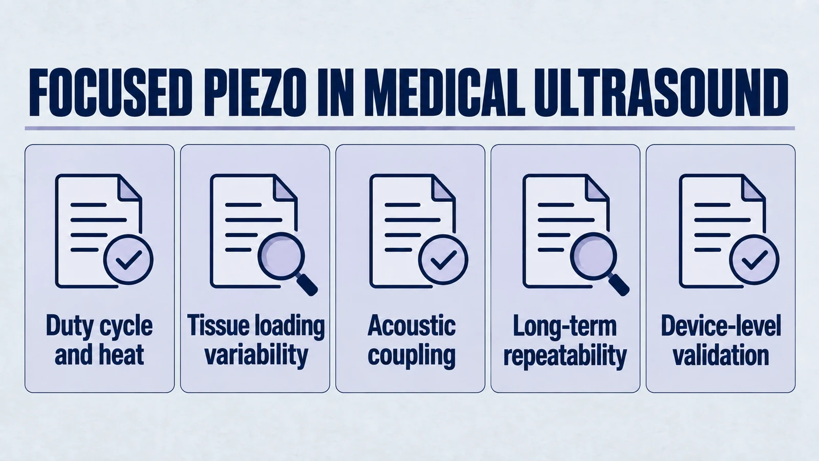
In medical ultrasound transducer design, viability is determined less by initial focal gain and more by:
- power density and thermal accumulation under real duty cycles,
- sensitivity to tissue loading and coupling variability,
- long-term stability and repeatability requirements,
- extended-operation failure modes that do not appear in early tests.
If you evaluate these constraints early, you can decide with engineering confidence whether to proceed with a focused ceramic design or pivot before burning months on prototypes that only worked in a water tank.
Need help reviewing geometry and stack constraints for your next transducer program? Our engineering team supports OEM feasibility studies from material selection to validation planning. Contact us through ultrasonic transducer supplier services or direct technical consultation.
Engineering decision notes
Focused and curved piezo ceramics
Use this article when curved ceramic geometry, focal distance, acoustic intensity, and assembly tolerances matter more than a flat element comparison. For "Focused Piezo Ceramics for Medical Ultrasound: Engineering Constraints That Determine W...", the practical value is in turning the topic into a measurable selection or sourcing decision.
YJ Piezo reviews curved ceramics as geometry-sensitive acoustic components, where aperture, curvature, thickness, electrode layout, and mounting boundary all affect the usable focus.
Selection checks
- Define focal distance, aperture, medium, and allowable package depth before selecting curvature.
- Review resonance behavior with the intended mounting boundary, not only as a loose ceramic.
- Plan sample validation around beam behavior, impedance spread, and thermal drift.
Failure risks
- A curved part can meet dimensional drawings but miss the intended acoustic focus if the boundary condition changes.
- Mode coupling can create unstable frequency behavior after assembly or thermal loading.
- Over-optimizing peak intensity can reduce practical tolerance to alignment and field conditions.
RFQ details
- What focal distance, aperture, and working medium are required?
- Is the ceramic bonded, clamped, housed, or used as a bare focused element?
- Do you need impedance spread, acoustic validation, or geometry tolerance records?
Relevant YJ Piezo pages
- Spherical Cap Piezoelectric Ceramics
Focused ceramic shapes for OEM ultrasonic assemblies
- Piezoelectric Ceramics
Shape and material options for custom design
- Air Acoustic Transducers
Acoustic interface references for beam behavior
Application FAQ
- Why are curved piezo ceramics harder to specify than flat ceramics?
- Curvature changes the acoustic field and can interact with mounting, bonding, and drive conditions. The useful specification must include geometry, focus, medium, resonance behavior, and assembly boundary.
- What should be validated before buying focused piezo ceramics in volume?
- Validate focal distance, impedance spread, frequency stability after assembly, thermal behavior, and the tolerance stack between ceramic geometry and the final housing.