
How to Choose the Radius of Curvature for Focused Piezo Ceramics
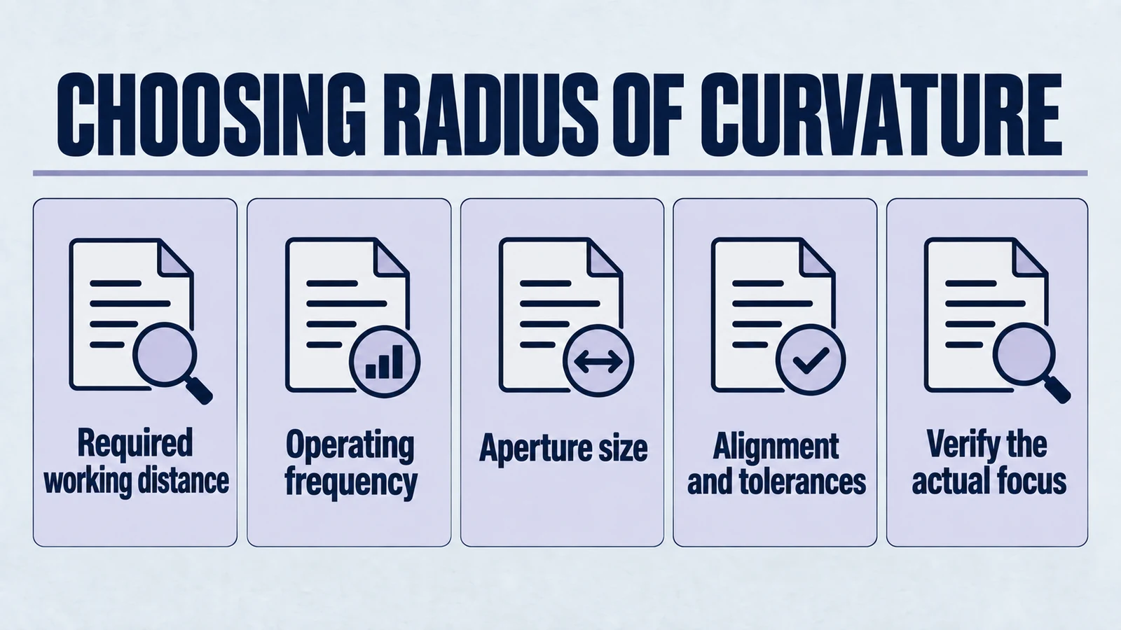
Audience: Engineers designing custom ultrasonic transducers
Goal: Help you pick a radius of curvature (ROC) that makes sense for your application, your medium, your manufacturing capability, and your test uncertainty.
Focused piezo ceramics are seductive. You pick a radius, the field "converges," the sensitivity jumps, and life is good. Until it isn't. In real transducers, ROC influences (1) focal distance, (2) beam width, and (3) how forgiving the design is to tolerance, mounting, and load variation. It also interacts with medium properties (speed of sound, attenuation, impedance), and with your ceramic's vibration mode, backing, and packaging.
This article is intentionally not a "plug numbers into one equation" guide. Those exist, they are useful, and they are also the fastest path to false confidence. Early-stage design needs a mental model that connects curvature to what you will actually measure on the bench.
Use this as a focused design guide: if you first need a broader comparison of discs, rings, tubes, rectangular plates, and focused curved parts, start with our geometry selection guide. This page is for the next step, when the real question is how radius of curvature should be chosen and reviewed.
Product path for this search intent
Match the article topic to the right YJ Piezo product page
Use this article when curved ceramic geometry, focal distance, acoustic intensity, and assembly tolerances matter more than a flat element comparison. For "How to Choose the Radius of Curvature for Focused Piezo Ceramics", the practical value is in turning the topic into a measurable selection or sourcing decision.
- Spherical Cap Piezoelectric Ceramics
Focused ceramic shapes for OEM ultrasonic assemblies
- Piezoelectric Ceramics
Shape and material options for custom design
- Air Acoustic Transducers
Acoustic interface references for beam behavior
1) What the Radius of Curvature Really Controls
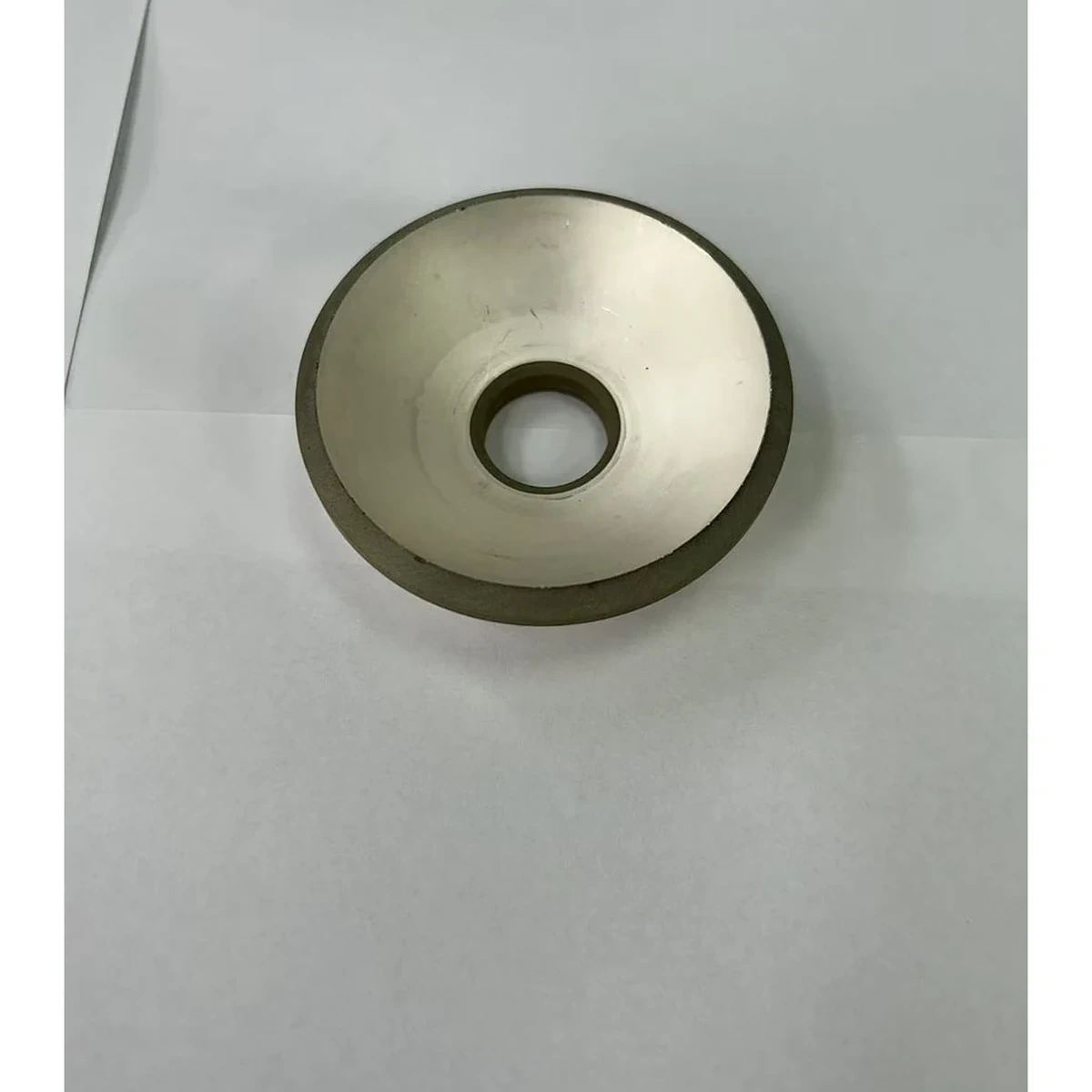
A focused ceramic is a curved radiating aperture. Its curvature introduces a phase profile that approximates a spherical wavefront. In the simplest picture, a smaller ROC means stronger curvature, which tends to:
- pull the focus closer to the ceramic.
- produce a narrower beam at focus.
- reduce the usable working range because the depth-of-focus shrinks.
A larger ROC does the opposite. It pushes the focus farther away, broadens the beam, and usually increases the depth-of-focus, but at the cost of peak intensity and sensitivity at any one point.
That is the basic trade. Then the real world adds layers. The "right" ROC is rarely the one that yields the maximum peak in an idealized field simulation. It is the one that yields repeatable performance across builds, fixtures, media, and standoff variation.
2) The First-Order Geometry: Useful, But Not a Finish Line
2.1 Spherical cap geometry
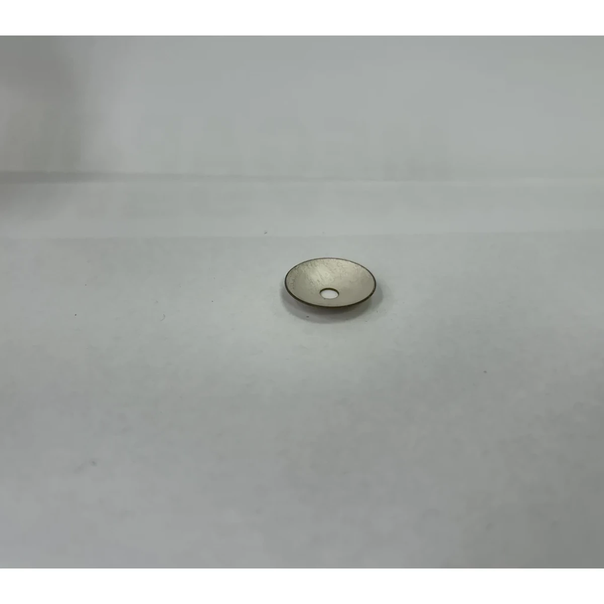
A typical focused element is a custom spherical-cap piezo ceramic. If you know the cap's aperture diameter (D) and sag height (h), the ROC (R) is:
Manufacturing often controls R more directly (tooling), while inspection often measures D and h. One reason this matters is that many "ROC mistakes" are actually sag mistakes caused by inconsistent forming or polishing, while radius tooling stayed nominal.
2.2 Geometric focus vs acoustic focus
A common first approximation is that the geometric focus is near R. For a thin radiating surface in a homogeneous medium, the focal distance is often treated as approximately the radius, sometimes adjusted by effective aperture and wave effects.
Here is the key. Geometric focus is not the same as acoustic focus.
The acoustic focus shifts because of:
- finite aperture diffraction.
- frequency, wavelength, and phase errors.
- boundary conditions (bond line, backing, housing).
- medium loading and impedance mismatch.
Use geometry to decide if you are in the right neighborhood. Then use acoustics to decide where your neighbors actually live.
2.3 A quick sanity check you can do before any simulation
If you change only ROC while keeping D fixed, ask yourself two questions:
- Does this move the nominal focus into a physically usable standoff range for my system?
- Can the required manufacturing tolerances realistically be held?
If the answer to either is "no," do not proceed to detailed modeling. You are optimizing a bad premise.
3) Curvature, Frequency, and Aperture: The "How Tight Is Tight" Question
Focused ultrasonics is not only about ROC. It is about ROC relative to aperture size and wavelength.
A practical way to think is via ratios:
- Aperture to curvature: D/R
- Aperture to wavelength: D/λ
If D is small compared to λ, you cannot get a sharp focus no matter how aggressive the curvature is. You will be diffraction-limited.
If D is large compared to λ, you can achieve a tighter focus, but you also become more sensitive to:
- geometric tolerances.
- alignment error.
- load variations.
In other words, high focusing capability comes with high fragility.
3.1 Why wavelength is the quiet dictator
A design that looks "strongly focused" in CAD can behave like a soft flashlight if λ is too large relative to the aperture. This comes up most often when engineers:
- choose frequency based on electronics convenience.
- inherit a legacy thickness-mode frequency without checking the aperture-limited beam physics.
- focus on ROC as the main knob while leaving D and f under-constrained.
Treat ROC as a placement tool. Treat D and f as the primary controls for spot size.
4) Medium Dependence: Water, Tissue, Air Are Different Planets
4.1 Speed of sound changes the effective wavelength
The fundamental relationship is:
Same frequency, different medium, different wavelength.
- Water: c is relatively high and stable. Wavelength is moderate.
- Tissue: c is similar order to water but attenuation is higher and dispersion may matter depending on band.
- Air: c is much lower, but the bigger problem is impedance mismatch and losses. Air is unforgiving.
Because λ changes, your D/λ and your achievable focal spot change. A design that focuses well in water may behave disappointingly in tissue if attenuation and scattering dominate. A design that "works on paper" in air may simply fail to couple energy.
4.2 Attenuation changes what "usable working range" means
Depth-of-focus is a geometric/acoustic concept. Usable range is an energy and SNR concept.
- In low-loss media (water), you can often exploit a longer working distance.
- In higher-loss media (tissue), peak intensity may occur near the surface, but practical SNR might peak elsewhere.
- In air, range is typically dominated by coupling strategy, matching layers, and system-level constraints.
So when you pick ROC, you are not only shaping the beam. You are positioning your energy where the medium can still deliver it.
4.3 Interfaces matter more than people want to admit
The medium is not only "what the wave travels through." It is also what the wave must cross. A water path with a thin window, a tissue path with layered interfaces, or an air path with a membrane can all shift focus and introduce aberration.
If your acoustic path includes interfaces, do not pretend the ROC alone defines your focal behavior. In early design, at least identify the likely dominant interface and decide whether you can control it.
5) Beam Width and Depth-of-Focus: What You Actually Control
Engineers care about three distances:
- Near field behavior close to the aperture.
- Focus location where beam diameter is minimized.
- Post-focus divergence.
A smaller ROC generally gives:
- smaller beam waist.
- shorter depth-of-focus.
- stronger sensitivity to error.
A larger ROC generally gives:
- larger beam waist.
- longer depth-of-focus.
- higher tolerance.
But beware the trap. "Longer depth-of-focus" does not by itself confirm "better performance." If your application needs high spatial selectivity, broad beams can destroy contrast. If your application needs energy at a specific depth, a too-broad focus spreads energy and raises required drive voltage.
5.1 Two different definitions of "working range"
In practice, teams often mix these up:
- Geometric working range: where the beam width stays within a specified multiple of the minimum.
- System working range: where the received signal, heating, cavitation threshold, or process outcome is acceptable.
ROC influences both. The second is often dominated by losses and coupling.
6) Tolerances and Design Compromises: Where Most Projects Win or Lose
6.1 ROC tolerance becomes phase error
A deviation in curvature causes phase error across the aperture. Phase error is what turns a tight focus into a fuzzy spot.
Practically, ROC tolerance interacts with:
- your operating frequency.
- your aperture diameter.
- your acceptable loss in peak intensity.
Higher frequency and larger apertures make the same absolute curvature error more damaging. A useful mental model is this: tight focus means you are relying on consistent phase alignment across the aperture. ROC error breaks that alignment.
6.2 Bond line thickness and adhesive uniformity
The adhesive layer introduces:
- added mass and stiffness.
- damping.
- nonuniform constraints.
If the bond line varies spatially, it becomes a phase and amplitude perturbation across the aperture. That is equivalent to "built-in defocus." This is why focused elements can behave inconsistently across builds even when the ceramic geometry is nominally correct.
If you only remember one thing: Bond line variation can easily dominate the effect of a small ROC tweak. That is why late-stage "ROC tuning" sometimes looks like random noise.
6.3 Electrode pattern and electrical boundary conditions
Curved elements are sometimes treated like "geometry only." But electrode coverage and segmentation influence mode purity and can create nonuniform drive. Nonuniform drive becomes nonuniform radiation. Nonuniform radiation becomes a degraded focus.
If your design uses wrap-around or partial electrodes for wiring convenience, treat that as a beam-shaping parameter. Not an afterthought.
6.4 Load sensitivity
Focused ceramics are often used in liquid-loaded transducers. Small changes in:
- standoff distance.
- coupling layer thickness.
- target boundary condition.
can shift effective focus and change amplitude response. If your system does not tightly control standoff, choosing an extremely tight focus can backfire.
6.5 Packaging and alignment: the silent beam killers
A rigid tilt or translation of an unchanged symmetric radiator in homogeneous fluid rotates or shifts its field; it does not inherently create astigmatism or split peaks. Clipping, interfaces, nonuniform bonding or deformation can alter the field. Separate alignment error from actual aberration and validate the assembled path.
If the assembly process cannot control alignment, choose ROC and aperture that keep performance acceptable under small angular errors. This is design, not wishful thinking.
6.6 A pragmatic compromise: pick ROC for range, then verify with test
A robust early-stage workflow:
- Pick an ROC that places the intended focus in the middle of your needed standoff range.
- Accept that the true peak may shift. Plan for it.
- Validate beam and impedance in the actual medium, with actual mounting.
- Adjust ROC or aperture if the design is too sensitive.
This sounds obvious. Many projects skip step 2 and pay for it later.
7) Sensitivity and Uncertainty: Why "One Perfect ROC" Is a Myth
Even with perfect machining, you still have uncertainty from:
- medium variability (temperature, composition).
- assembly variation.
- boundary conditions (housing, backing, potting).
- measurement method and fixture repeatability.
The more aggressive the focusing (small ROC, large aperture, high frequency), the more those uncertainties dominate performance.
So the right question is rarely "What ROC gives the tightest focus." It is usually:
"What ROC gives enough focus while staying buildable, repeatable, and stable in my operating environment."
7.1 What instability looks like on the bench
If your chosen ROC is too aggressive for your build and test reality, you often see:
- focus location that moves run-to-run even with the same part.
- strong sensitivity to small standoff changes.
- beam maps that show multiple local maxima instead of one clean peak.
- impedance signatures that shift after potting or after thermal cycling.
These are not "bad luck." They are signals that the design is operating too close to the edge.
8) Design Rules of Thumb: Use Them as Guardrails, Not as Answers
These are not laws. They are sanity checks.
- If your application has variable standoff, avoid extremely tight focal designs. Favor a longer usable range.
- If you need high spatial selectivity, prioritize aperture and wavelength. Then choose ROC that does not exceed your tolerance capability.
- If you operate in high-loss media, place focus closer than you would in water. Otherwise attenuation eats your gain.
- If you cannot control assembly variation (bond line, seating, alignment), pick a less aggressive ROC. Repeatability beats peak performance.
A blunt but useful principle: if your manufacturing and test system is not mature, choose an ROC that gives you engineering slack. Later, when you can control variation, you can chase peak performance.
9) A Practical Early-Stage Decision Process
Step A: Define your "working requirement" in engineering terms
You need three numbers, not one.
- Target working distance range (min to max)
- Required lateral resolution (spot size or beam width)
- Required acoustic output or receive sensitivity at that range
Add a fourth if you can: your allowable variation. If your system can tolerate ±0.5 mm standoff but not ±2 mm, that changes the ROC choice.
Step B: Choose frequency first, then aperture, then ROC
Frequency and aperture heavily constrain what focusing is physically possible.
- Frequency sets wavelength and attenuation regime.
- Aperture sets focusing potential and near-field behavior.
- ROC then shapes where the energy concentrates and how fragile the result is.
If you start with ROC, you are choosing "where the focus should be" before you know whether a focus of that quality is achievable.
Step C: Build a first-pass uncertainty budget
You do not need a full metrology program. You need a rough list:
- ROC tolerance and sag tolerance
- thickness tolerance and resonance spread
- bond line thickness variation
- alignment tolerance
- medium variability (temperature, composition)
Then ask: which term is likely the biggest? If it is bond line or alignment, do not waste effort fine-tuning ROC to the third decimal.
Step D: Treat ROC as a tunable parameter, not a sacred constant
Plan iterations:
- ROC v1 to hit range and buildability.
- ROC v2 if you need tighter beam.
- Possibly redesign aperture if ROC alone cannot deliver.
If your project timeline cannot tolerate iteration, do not choose an ultra-tight focus. Tight focus is an optimization, not a prerequisite.
10) How to Validate ROC Choices Without Fooling Yourself
Validation does not mean "one beautiful beam plot." It means repeatable results under controlled conditions.
10.1 Control the test geometry
- Define a reference standoff.
- Control temperature.
- Use consistent coupling.
- Keep fixturing rigid and repeatable.
If the test setup drifts, you will attribute fixture errors to ROC.
10.2 Measure both field and electrical behavior
- Beam mapping tells you what the acoustic output looks like.
- Impedance and phase tell you how loading and assembly changed the element.
When those disagree, the transducer is telling you a story. Listen.
10.3 Confirm the medium assumption
If you are designing for tissue-equivalent media or a process fluid, do not validate only in clean water and call it done. The ROC decision is medium-dependent.
11) What to Provide When You Request a Custom Focused Ceramic
To get a meaningful design response from a manufacturer, provide:
- Medium (water, tissue-equivalent, air, oil) and temperature range
- Operating frequency band and duty cycle
- Target working distance range and required spot size
- Aperture diameter constraints and housing limits
- Mounting method (bonding, clamping, potting) and backing concept
- Electrode and wiring constraints
- Tolerance priorities (ROC tolerance, thickness tolerance, electrode pattern)
If you only provide ROC and thickness, you are asking for a geometry part. Not an engineering part.
Closing
Choosing the radius of curvature is not a single-equation problem. It is a design negotiation between physics, medium behavior, manufacturing tolerances, and system-level constraints.
If you want, share your target medium, frequency, aperture constraints, and working distance range. We can sanity-check whether your planned ROC is likely to be stable, or likely to turn into a "works in simulation, fails in assembly" situation.
Related reading:
- How Does a Bowl-Shaped Piezo Ceramic Focus Ultrasound?
- Spherical Cap vs Hemispherical Piezo Ceramics
- When Not to Use Focused Piezoelectric Ceramics
- Spherically Curved Piezoelectric Ceramics: A Practical Introduction
- Selecting Piezo Ceramics for Continuous Duty Applications
If you are evaluating focused ceramic designs and need engineering support, our team can review your application requirements and recommend ROC, aperture, and material combinations that balance performance with manufacturing reality.
Engineering decision notes
Focused and curved piezo ceramics
Use this article when curved ceramic geometry, focal distance, acoustic intensity, and assembly tolerances matter more than a flat element comparison. For "How to Choose the Radius of Curvature for Focused Piezo Ceramics", the practical value is in turning the topic into a measurable selection or sourcing decision.
YJ Piezo reviews curved ceramics as geometry-sensitive acoustic components, where aperture, curvature, thickness, electrode layout, and mounting boundary all affect the usable focus.
Selection checks
- Define focal distance, aperture, medium, and allowable package depth before selecting curvature.
- Review resonance behavior with the intended mounting boundary, not only as a loose ceramic.
- Plan sample validation around beam behavior, impedance spread, and thermal drift.
Failure risks
- A curved part can meet dimensional drawings but miss the intended acoustic focus if the boundary condition changes.
- Mode coupling can create unstable frequency behavior after assembly or thermal loading.
- Over-optimizing peak intensity can reduce practical tolerance to alignment and field conditions.
RFQ details
- What focal distance, aperture, and working medium are required?
- Is the ceramic bonded, clamped, housed, or used as a bare focused element?
- Do you need impedance spread, acoustic validation, or geometry tolerance records?
Relevant YJ Piezo pages
- Spherical Cap Piezoelectric Ceramics
Focused ceramic shapes for OEM ultrasonic assemblies
- Piezoelectric Ceramics
Shape and material options for custom design
- Air Acoustic Transducers
Acoustic interface references for beam behavior
Application FAQ
- Why are curved piezo ceramics harder to specify than flat ceramics?
- Curvature changes the acoustic field and can interact with mounting, bonding, and drive conditions. The useful specification must include geometry, focus, medium, resonance behavior, and assembly boundary.
- What should be validated before buying focused piezo ceramics in volume?
- Validate focal distance, impedance spread, frequency stability after assembly, thermal behavior, and the tolerance stack between ceramic geometry and the final housing.