
Optimizing Conveyor Systems: M18 vs. M30 Sensor Selection Guide
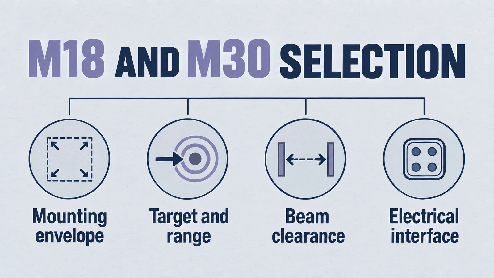
1. Introduction: The Sensory Backbone of Modern Intralogistics
In the rapidly evolving landscape of industrial automation, the conveyor system has transitioned from a simple transport mechanism to a sophisticated, data-rich logistical artery. The efficacy of modern intralogistics—characterized by high-speed sortation, zero-pressure accumulation, and autonomous routing—rests fundamentally on the reliability of its sensory feedback loops. Within this domain, the selection of object detection technology is not merely a peripheral component choice; it is a foundational architectural decision that dictates the system's Overall Equipment Effectiveness (OEE), throughput capability, and maintenance latency.
While photoelectric sensors have historically dominated simple presence detection, the increasing complexity of target materials in modern supply chains has exposed the limitations of optical technology. The proliferation of transparent polyethylene terephthalate (PET) clamshells, highly reflective polybags, dark light-absorbing automotive components, and dust-laden environments in bulk material handling has necessitated a shift toward acoustic sensing modalities. Ultrasonic sensors, leveraging the mechanical propagation of sound waves (phonons) rather than electromagnetic radiation (photons), offer a robust alternative capable of detecting mass and density independent of optical surface properties.
This engineering report, commissioned for the technical community surrounding Yujie Piezo Technology, serves as a definitive guide for machine builders, OEM designers, and automation engineers tasked with instrumenting the next generation of conveyor systems. The central dialectic of this analysis is the rigorous comparison between the two industry-standard form factors: the compact M18 (18mm cylindrical) and the robust M30 (30mm cylindrical) ultrasonic sensors. Often treated as interchangeable based solely on mechanical fit, these two platforms represent distinct acoustic classes with divergent beam characteristics, energy potentials, and integration constraints.
Product path for this search intent
Match the article topic to the right YJ Piezo product page
Use this article when sensor performance depends on target distance, beam angle, housing material, liquid behavior, or false echo control. For "Optimizing Conveyor Systems: M18 vs. M30 Sensor Selection Guide", the practical value is in turning the topic into a measurable selection or sourcing decision.
- Ultrasonic Sensors
Distance, level, and detection sensor portfolio
- Flow Measurement Transducers
Bubble and flow-related ultrasonic sensing paths
- Air Acoustic Transducers
Air-coupled transducers for range and presence detection
By dissecting the underlying physics of piezoelectric transduction, analyzing the beam propagation mechanics inherent to 18mm and 30mm apertures, and mapping these attributes to real-world conveyor failure modes, this report aims to provide a granular, actionable selection framework. We will explore the Yujie MU18 and MU30 product series as reference architectures, examining how their specific electromechanical properties influence performance in applications ranging from high-speed box singulation to bulk aggregate profiling.
2. Fundamental Acoustics and Piezoelectric Physics
To accurately adjudicate the engineering trade-offs between M18 and M30 sensors, the automation engineer must first possess a nuanced understanding of the acoustic physics that govern their operation. The distinction between these form factors is rooted in the immutable laws of wave propagation and electromechanical coupling.
2.1 The Piezoelectric Transducer: Scaling Effects
At the core of every ultrasonic sensor lies the piezoelectric ceramic element, typically composed of lead zirconate titanate (PZT). This material exhibits the piezoelectric effect, where mechanical deformation is induced by an applied electric field (transmission) and, conversely, an electric charge is generated by mechanical stress (reception). The efficiency of this energy conversion is quantified by the electromechanical coupling factor (k), a parameter critical to sensor performance.
The geometric constraints of the M18 and M30 housings dictate the maximum dimensions of this ceramic element, which in turn determines the sensor's resonant frequency and acoustic power output.
- The M18 Constraint: An M18 sensor, with an 18mm external diameter, typically houses a transducer disk with a diameter (D) between 12mm and 14mm. To achieve efficient resonance in this smaller mass, the ceramic is designed to vibrate at higher frequencies, typically in the range of 200 kHz to 400 kHz.
- The M30 Advantage: The M30 sensor, with a 30mm external diameter, accommodates a significantly larger transducer disk, often 20mm to 25mm in diameter. The increased mass and surface area allow for resonance at lower frequencies, typically 80 kHz to 200 kHz, while enabling the generation of higher sound pressure levels (SPL) due to the larger radiating surface.
This scaling effect is non-trivial. The acoustic impedance matching between the PZT ceramic (high impedance) and the air (low impedance) is mediated by a matching layer on the sensor face. The efficiency of this matching layer is frequency-dependent. The larger surface area of the M30 transducer allows for a more favorable impedance match, resulting in greater energy transfer into the air and, consequently, higher excess gain for detecting difficult targets.
2.2 Frequency-Dependent Attenuation
The propagation of ultrasonic waves in air is subject to attenuation caused by viscous friction, thermal conduction, and molecular relaxation processes. This attenuation is heavily dependent on frequency. The absorption coefficient α (measured in dB/m) increases approximately with the square of the frequency (f²).
This physical relationship creates a hard limit on the sensing range of the M18 platform relative to the M30.
- M18 (300 kHz): experiences high atmospheric attenuation. The signal energy dissipates rapidly over distance. Consequently, M18 sensors are generally limited to sensing ranges under 1.3 meters (Yujie MU18 series) to maintain a usable signal-to-noise ratio (SNR).
- M30 (100 kHz): experiences significantly lower attenuation. The acoustic pulse retains its energy over much longer distances, enabling sensing ranges of 6 meters to 8 meters (Yujie MU30 series).
For conveyor applications, this dictates that any requirement for "high bay" overhead detection or long-range silo monitoring automatically necessitates the M30 form factor, not merely due to "power," but due to the fundamental physics of atmospheric absorption.
2.3 Beam Divergence and Diffraction
The shape of the ultrasonic beam—the "cone" of detection—is determined by the diffraction of waves from the circular aperture of the transducer. The beam divergence angle (θ), which represents the half-angle where the sound pressure drops by 3dB, is approximated by the ratio of the wavelength (λ) to the transducer diameter (D):
This equation reveals the complex interplay between sensor size and frequency:
- M18: Small D, but also small λ (high frequency).
- M30: Large D, but also large λ (low frequency).
Thread size alone does not establish frequency, aperture, beam width or target range. For a circular aperture in the usual piston approximation, near-field length is approximately D²/(4λ): at fixed aperture diameter, a longer wavelength shortens it. Compare the exact sensor’s target-dependent beam diagrams, aperture, frequency and validated detection range rather than inferring these properties from M18 or M30 housing threads.
2.4 The Blind Zone (Dead Band) Mechanics
Immediately adjacent to the sensor face is the "Blind Zone," a region where object detection is impossible. This is caused by the mechanical "ringing" of the piezoelectric ceramic. After the excitation voltage is removed, the ceramic continues to oscillate due to its inertia, much like a bell after being struck. During this ring-down time (tring), the sensor cannot switch to receive mode, as the self-generated noise masks any returning echoes.
- M18 Dynamics: The smaller, lighter ceramic mass of the MU18 sensor has lower inertia, resulting in a faster decay of oscillations. This leads to a significantly shorter blind zone, typically 20mm to 100mm.
- M30 Dynamics: The massive ceramic element of the MU30 possesses greater mechanical inertia. The ring-down time is longer, resulting in a larger blind zone, typically 200mm to 350mm.
This parameter is often the deciding factor in compact conveyor machinery, where sensors must be mounted in close proximity to the passing rollers or belts.
3. The M18 Platform: Precision in Compact Spaces
The M18 ultrasonic sensor represents the scalpel of the automation engineer's toolkit. It offers high precision, fast response, and compact integration, making it the preferred choice for detailed object manipulation tasks within the conveyor ecosystem.
3.1 Yujie MU18 Technical Profile
The Yujie MU18 series exemplifies the capabilities of the 18mm form factor. Designed for "near-field" logistics, these sensors prioritize resolution and speed over raw power.
- Housing: Nickel-plated brass or PBT plastic, 18mm x 60mm.
- Sensing Range: 30mm to 1000mm.
- Frequency: ~300 kHz.
- Resolution: < 1mm (due to short wavelength).
- Response Time: < 20ms.
3.2 Application: High-Speed Singulation and Gapping
In high-speed induction conveyors, products must be spaced (singulated) with precise gaps to ensure proper scanning by barcode readers or weighing by dynamic scales. The conveyor belt may move at speeds exceeding 2.0 m/s.
The Engineering Challenge:
At 2.0 m/s, a sensor with a slow response time introduces significant position error. If a sensor takes 100ms to process the echo and switch the output, the box has traveled 200mm (d=vt). This error margin is unacceptable for precision gapping.
The M18 Solution:
The MU18, operating at 300 kHz, can emit pulse bursts at a higher repetition rate than a low-frequency sensor. This allows for a faster update cycle. With a response time of 15ms, the position error is reduced to just 30mm, which is easily compensated for in the PLC logic. Furthermore, the small blind zone (e.g., 50mm) allows the sensor to be mounted directly on the side rail or immediately above the belt without requiring complex stand-off brackets that would vibrate at high speeds.
3.3 Application: Transparency Detection on Roller Conveyors
Detecting clear plastic trays or polybags on a roller conveyor is a notorious failure point for optical sensors. The laser beam passes through the tray, striking the roller below and signaling "All Clear" when a jam is actually forming.
The M18 Geometry:
The pitch (spacing) between conveyor rollers is a critical geometric constraint. Standard roller pitches (e.g., 50mm, 75mm) leave very little gap for sensor mounting.
- M30 Fit: An M30 sensor (30mm diameter) mounted between rollers with a 50mm pitch leaves only 10mm of clearance on either side. This proximity to the rotating metal rollers can cause acoustic reflections (side lobe interference) or mechanical fouling if a bearing fails and the roller wobbles.
- M18 Fit: The M18 sensor fits comfortably in the inter-roller gap. Its narrower beam (initially) ensures the sound travels up through the gap without hitting the adjacent rollers. The ultrasonic wave reflects off the bottom of the clear plastic tray—regardless of transparency—providing a 100% reliable "Presence" signal.
3.4 Application: Bottle and Can Counting
In beverage industry conveyors, the targets are highly curved (aluminum cans) or complex (glass bottles).
- Wavelength Physics: To detect a curved surface reliably, the sensing wavelength should ideally be smaller than the radius of curvature to minimize scattering. The M18's high frequency (short λ) is superior to the M30 (long λ) for resolving the presence of small, curved containers.
- Beam Spot: The M18's focused beam can be directed at the neck of a bottle to count individual units in a dense queue, whereas an M30's wide beam would overlap multiple bottles, blurring the count.
4. The M30 Platform: Power and Environmental Immunity
If the M18 is the scalpel, the M30 is the sledgehammer. It is designed for brute force sensing: punching through dust, ignoring small interferences, and detecting difficult targets at long ranges.
4.1 Yujie MU30 Technical Profile
The Yujie MU30 series leverages the larger housing volume to integrate larger transducer elements and more robust shielding.
- Housing: Stainless steel (316L option) or PBT, 30mm x 100mm.
- Sensing Range: 200mm to 6000mm (up to 8m for select models).
- Frequency: ~80 kHz - 120 kHz.
- Acoustic Power: High SPL (Sound Pressure Level).
- Protection: Often IP67 / IP69K for washdown environments.
4.2 Application: Bulk Material Profiling
In mining, agriculture, and aggregate processing, conveyors transport bulk solids (coal, grain, wood chips). The goal is often not just to detect "presence" but to measure the "profile" or volume of the material on the belt to regulate crusher feed rates.
The Engineering Challenge:
- Dust: These environments are choked with airborne particulate. High-frequency sound (M18) is scattered by dust particles (Rayleigh scattering) if the particle size is comparable to the wavelength.
- Irregular Surface: A pile of rock is not a flat reflector. It scatters sound in all directions. A weak sensor will not receive enough echo energy to trigger.
- Distance: The sensor must be mounted high (2-3 meters) to clear the material surges and machinery.
The M30 Solution:
The MU30's lower frequency (100 kHz) creates waves much longer than typical dust particles, allowing the wave to diffract around the dust with minimal attenuation. The high acoustic power ensures that even the scattered echoes from the irregular rock pile are strong enough to be detected. The large "footprint" of the M30 beam on the material surface integrates the height over a larger area, providing a stable average level rather than a noisy signal that jumps with every individual rock.
4.3 Application: Catenary Sag Monitoring
Heavy conveyor belts, particularly in mining, are tensioned between idlers. If the tensioning system fails, the belt can sag excessively between rollers, leading to severe derailment or structural damage.
The M30 Geometry:
To monitor sag, sensors are mounted under the belt or to the side, looking across long spans. The range required is often 2 to 4 meters. The M18 is physically incapable of this range. The M30, mounted on the structural truss, monitors the vertical position of the belt. If the belt droops below a set threshold, the M30 triggers an emergency stop. The M30's vibration resistance (due to its higher mass and robust mounting threads) is also critical here, as the conveyor frame vibrates heavily during operation.
4.4 The Self-Cleaning Phenomenon
A unique advantage of the M30 sensor in dirty conveyor environments is the Self-Cleaning Effect. The transducer face of an M30 sensor vibrates with a significantly higher amplitude (displacement) than an M18 sensor due to the higher drive voltage and larger ceramic element. This vigorous mechanical excursion prevents dust, flour, or sawdust from adhering to the sensor face. In contrast, the high-frequency, low-amplitude vibration of an M18 face can allow fine particulates to cake onto the surface, eventually damping the sensor to the point of failure. For conveyors handling flour, cement, or gypsum, the M30 is the mandatory choice for maintenance reduction.
5. Comparative Engineering: The Selection Decision Matrix
The decision between M18 and M30 is rarely about "one is better than the other"; it is about matching the physical attributes of the sensor to the constraints of the application.
5.1 Beam Width vs. Conveyor Geometry (The Side Rail Conflict)
One of the most frequent failure modes in conveyor automation is the Side Rail False Positive. Conveyors are flanked by guard rails to contain products. Ultrasonic sensors emit sound in a conical lobe.
- The Geometry of Failure: Consider an overhead sensor mounted 1.5 meters above a conveyor belt that is 600mm wide. An M30 sensor with a 10° half-angle beam will have a beam radius of r = h × tan(10°) ≈ 260mm at the belt. The total beam width is ~520mm. This is dangerously close to the 600mm width of the conveyor. If the sensor is slightly misaligned, or if the beam has side lobes, the sound will hit the steel side rails. The rail is a "hard" reflector (steel). The box is a "soft" reflector (cardboard). The sensor will lock onto the rail and report "Blocked" permanently.
- The M18 Advantage: An M18 sensor, typically mounted closer (e.g., 800mm) due to its range limits, and having a tighter effective beam due to lower power, is much easier to aim "down the middle" of the conveyor without clipping the rails. For narrow conveyors (< 500mm), the M18 is geometrically superior.
- The M30 Mitigation: If an M30 must be used (e.g., for target material reasons), the engineer must utilize:
- Beam Width Adjustment: Advanced Yujie M30 sensors with IO-Link allow the user to electronically reduce the sensitivity, effectively narrowing the beam.
- Sound Pipe/Horn: Attaching a physical focusing horn to the M30 face to mechanically constrain the side lobes.
5.2 Comparative Data Table
| Feature | Yujie M18 Series (MU18) | Yujie M30 Series (MU30) | Engineering Implication for Conveyors |
|---|---|---|---|
| Typical Range | 30 mm – 1,300 mm | 200 mm – 8,000 mm | M18 for gap checking/singulation; M30 for high-bay/silo. |
| Blind Zone | 20 mm – 100 mm | 200 mm – 600 mm | M18 fits between rollers; M30 needs stand-off brackets. |
| Operating Frequency | 200 kHz – 400 kHz | 80 kHz – 200 kHz | M18 resolves small gaps; M30 penetrates dust/air currents. |
| Beam Stability | High precision, susceptible to air currents | High stability, resistant to cross-wind | M30 preferred near dock doors or cooling fans. |
| Response Time | Fast (< 20 ms) | Moderate (> 80 ms) | M18 mandatory for belt speeds > 1 m/s. |
| Dirt Immunity | Moderate | High (Self-Cleaning) | M30 mandatory for bulk solids/mining. |
| Vibration | Low Mass (High Resonance) | High Mass (Low Resonance) | M18 simpler to mount; M30 needs rigid truss. |
6. Mechanical Integration: Mastering Vibration and Resonance
Conveyor systems are inherently vibratory environments. The rhythmic impact of rollers, the oscillation of chains, and the hum of VFD-driven motors create a noise spectrum that can mechanically compromise sensors.
6.1 The Cantilever Resonance Problem
A common error in deploying M30 sensors is the "Cantilever Mount." Engineers often mount the heavy M30 sensor (which can weigh 200g-300g in stainless steel) on a long, L-shaped bracket to achieve the necessary stand-off distance to clear the blind zone.
- Physics of Failure: This setup forms a spring-mass system. If the natural frequency of the bracket-sensor assembly matches the vibration frequency of the conveyor (e.g., 30 Hz), the sensor will oscillate violently.
- Acoustic Consequence: The beam "wags" up and down. At the peak of the oscillation, the beam might miss the target entirely or hit the floor/roller, causing intermittent false triggers that are nightmares to diagnose.
- Piezo Fatigue: Prolonged exposure to resonant vibration can crack the piezoelectric ceramic element or sever the internal bonding wires, leading to premature sensor death.
6.2 Optimization Strategy
- For M30: Avoid simple L-brackets. Use Truss Mounts or Bridge Clamps that secure the sensor from two points, increasing the stiffness of the mount and pushing the resonant frequency above the conveyor's vibration spectrum.
- For M18: The low mass (~40g-60g) of the M18 sensor makes it less susceptible to self-resonance. Standard brackets are usually sufficient, provided they are tightened to the specified torque to prevent rotation.
6.3 Mounting Orientation and Debris
- Looking Up (Between Rollers): often practical for M18. Must use an air purge or angled deflector to prevent dust accumulation.
- Looking Down (Overhead): Preferred for M30. Gravity keeps the face clean.
- Looking Across (Side Frame): Viable for both. However, M30 sensors protruding from the side rail are prone to impact damage from forklifts or passing AGVs (Automated Guided Vehicles). Flush-mount M18 sensors recessed into the rail profile are the safer choice here.
7. Electrical Integration: IO-Link and Smart Sensing
The choice between M18 and M30 is increasingly influenced by the connectivity layer. The integration of IO-Link (IEC 61131-9) has changed how these sensors are deployed and diagnosed in smart factories.
7.1 Virtualizing the Sensor
Historically, M30 sensors were "dumb" devices with a potentiometer for gain adjustment. Yujie's modern IO-Link enabled M30 sensors allow for virtual reconfiguration.
- Beam Shaping: An engineer can use IO-Link parameters to digitally narrow the beam width of an M30 sensor, allowing it to be used in a narrow conveyor lane where previously only an M18 would fit, while retaining the M30's superior power and self-cleaning face.
- Foreground/Background Suppression: IO-Link allows for the teaching of complex window modes. For example, "Ignore the roller at 1000mm, ignore the side rail at 300mm, only detect objects in the 400mm-800mm window."
7.2 Predictive Maintenance Data
IO-Link sensors provide real-time diagnostic data that is crucial for conveyor uptime.
- Signal Strength/Echo Quality: A gradual decline in echo strength over weeks indicates dust buildup on the lens. The PLC can trigger a maintenance alarm ("Clean Sensor 34") before the sensor fails to detect a box.
- Temperature Monitoring: Internal temperature sensors can warn of overheating in motor control cabinets or high ambient heat that might affect the speed of sound compensation.
8. Failure Modes and Effect Analysis (FMEA)
To design a robust system, one must understand how it fails. We present a detailed Failure Mode and Effect Analysis for ultrasonic sensors in conveyor environments.
8.1 Failure Mode: Acoustic Cross-Talk
- Scenario: High-density accumulation zones where multiple sensors are mounted close together (e.g., every 500mm).
- Mechanism: Sensor A emits a pulse. Sensor B, located 500mm downstream, receives Sensor A's pulse and interprets it as a reflection from a nearby object. Sensor B triggers falsely.
- Vulnerability: M30 sensors, with their higher power and wider side lobes, are significantly more prone to cross-talk than M18 sensors.
- Mitigation:
- Synchronization: Hard-wire the sync pins of Yujie sensors together. They will fire simultaneously, effectively blinding them to each other's pulses (as they are both in "transmit" mode, not "receive" mode).
- Multiplexing: Configure the sensors (via IO-Link) to fire sequentially. A -> B -> C -> A. This eliminates cross-talk but reduces the system's overall response speed.
- Frequency Shift: Alternate between M18 (300 kHz) and M30 (100 kHz) sensors in the line. They will be acoustically invisible to each other.
8.2 Failure Mode: The "Soft Target" Absorption
- Scenario: Conveying open-cell foam, stacks of textiles, or loose wool.
- Mechanism: The target material absorbs the acoustic energy rather than reflecting it. No echo returns to the sensor.
- Vulnerability: M18 sensors, with lower initial SPL, are most likely to fail here. The weak signal is completely absorbed.
- Mitigation:
- Use M30: The high-energy pulse of the M30 is more likely to generate a return echo even from absorptive materials.
- Reflective Mode: Switch to a Retro-Reflective ultrasonic configuration. The sensor looks at a hard reflector (e.g., the conveyor floor or a metal plate). The soft object is detected because it blocks the signal, not because it reflects it.
8.3 Failure Mode: Specular Reflection (The "Stealth" Box)
- Scenario: Conveying flat, smooth objects (e.g., sheet metal, polished plastic crates) that are slightly tilted.
- Mechanism: If the smooth surface is angled greater than ~10° relative to the sensor face, the sound wave deflects away from the sensor (Angle of Incidence = Angle of Reflection). The sensor sees nothing.
- Mitigation:
- M30 Wide Beam: The wider beam of the M30 increases the probability that some portion of the wavefront will strike the object perpendicularly and return.
- Mounting Angle: Intentionally mount the sensor perpendicular to the most common object surface, or use multiple sensors at different angles (diversity reception).
8.4 Failure Mode: Thermal Drift
- Scenario: A warehouse conveyor that runs from a cold storage freezer (-20°C) to a loading dock (+30°C).
- Mechanism: The speed of sound in air changes by roughly 0.17% per °C. A 50°C temperature swing causes an 8.5% error in distance measurement. On a 2-meter measurement (M30), this is a 17cm error—enough to miss a box height threshold.
- Vulnerability: M30 metal housings have high thermal mass and can lag behind the actual air temperature, causing the internal temperature compensation algorithm to be inaccurate during rapid temperature changes.
- Mitigation: Use Yujie sensors with external temperature probe inputs or IO-Link temperature data correction. For extreme gradients, use M18 plastic sensors which have lower thermal mass and equilibrate faster.
9. Comprehensive Application Scenarios
To synthesize this technical data into actionable advice, we examine three canonical conveyor scenarios.
Scenario A: The "Gap Check" on High-Speed Roller Conveyor
- Requirement: Detect gaps between boxes to prevent jams at the diverter.
- Constraints: Roller pitch 60mm. Belt speed 2.5 m/s.
- Selection: Yujie MU18 High-Speed Series.
- Reasoning:
- Fit: The 18mm body fits in the 60mm roller gap.
- Speed: The 2.5 m/s speed demands the <15ms response time of the MU18. An M30 would be too slow.
- Blind Zone: The sensor is mounted just 20mm below the pass line. The MU18's 20mm blind zone allows detection.
- Mounting: Between rollers, angled 5° upstream to prevent direct reflection from the ceiling when the gap is empty.
Scenario B: Hopper Level Control for Grain Conveyor
- Requirement: Maintain a constant head of grain in the feed hopper.
- Constraints: Extremely dusty. Vibration from the crusher. Range 3 meters.
- Selection: Yujie MU30 Stainless Steel (IP69K).
- Reasoning:
- Environment: The dust would blind an optical sensor and attenuate an M18 ultrasonic sensor. The M30's 100 kHz wave penetrates the dust.
- Self-Cleaning: The M30 face shakes off the grain dust.
- Range: 3 meters is well beyond M18 capability.
- Mounting: Suspended on a vibration-dampened truss bridge to isolate it from the crusher tremors.
Scenario C: Pallet Detection in Cold Storage (-30°C)
- Requirement: Detect wooden pallets on a chain conveyor.
- Constraints: Deep freeze. Frost accumulation.
- Selection: Yujie MU30 with Heated Face (Specialty) or M30 Standard with High Excess Gain.
- Reasoning:
- Target: Wood is porous and absorbs sound. The M30's power is needed.
- Frost: Frost on the sensor face acts as a dampener. The high-energy vibration of the M30 helps crack and shed frost.
- Temperature: Standard M30 sensors are often rated to -25°C or -40°C, whereas compact M18s often bottom out at -20°C due to internal component density.
10. Conclusion: The Path to Optimized Selection
The selection of ultrasonic sensors for conveyor systems is not a binary choice between "Small" and "Large." It is a multi-dimensional optimization problem involving acoustics, mechanics, and environmental resilience.
Selection Summary
The Yujie M18 Series is the instrument of precision. It is the optimal choice for:
- Space-constrained zones: Between rollers, inside side rails.
- High-speed applications: Singulation, counting, edge detection.
- Near-field targets: Objects < 1 meter away.
- Hard, defined targets: Bottles, cans, plastic trays.
The Yujie M30 Series is the instrument of resilience. It is the optimal choice for:
- Hostile environments: Dust, outdoor weather, washdown zones.
- Difficult targets: Bulk solids, sound-absorbing foam, irregular pallets.
- Long-range monitoring: Silo levels, belt sag, overhead detection > 2 meters.
- Structural Robustness: Areas prone to impact or heavy mechanical load.
For the automation engineer, the "Best" sensor is the one that disappears—the one that functions so reliably within its physical envelope that it is never noticed by the maintenance team. By adhering to the physics-based selection criteria outlined in this guide, machine builders can ensure their conveyor systems achieve that level of invisible, flawless performance.
References: Yujie Piezo Technology technical archives, IEC standard 60947-5-2 (Proximity switches), and field application reports from conveyor OEM partners.
Related Technical Resources
Use these internal references to compare geometry, material selection, reliability testing, and sourcing decisions.
- Piezoelectric Disc Products
- Piezoelectric Ring Products
- Piezoelectric Tube Products
- Ultrasonic Transducer Supplier Overview
- Piezoelectric Material Selection Guide
- Contact the Engineering Team
- Spherically Curved Piezoelectric Ceramics: Practical Introduction
- How Bowl-Shaped Piezo Ceramics Focus Ultrasound
Engineering decision notes
Ultrasonic sensing and detection
Use this article when sensor performance depends on target distance, beam angle, housing material, liquid behavior, or false echo control. For "Optimizing Conveyor Systems: M18 vs. M30 Sensor Selection Guide", the practical value is in turning the topic into a measurable selection or sourcing decision.
YJ Piezo treats ultrasonic sensing as an acoustic interface problem: transducer frequency, beam shape, housing, drive electronics, and target environment are reviewed together.
Selection checks
- Define target range, dead zone, beam angle, and mounting geometry before choosing the sensor family.
- Check the medium, target surface, temperature swing, foam, vapor, and side-wall risk.
- Separate detection repeatability from ideal lab accuracy when the sensor will operate in a tank, tube, or moving line.
Failure risks
- A sensor can pass bench distance tests and still fail in tanks with foam, agitation, vapor, or narrow geometry.
- Changing only frequency without reviewing beam angle and mounting can increase false echoes.
- Ignoring housing material or sealing requirements can shorten lifetime in washdown or chemical environments.
RFQ details
- What is the minimum and maximum detection distance?
- Is the target liquid, solid, sheet material, air flow, or a moving object?
- What temperature, humidity, IP rating, and output signal does the system require?
Relevant YJ Piezo pages
- Ultrasonic Sensors
Distance, level, and detection sensor portfolio
- Flow Measurement Transducers
Bubble and flow-related ultrasonic sensing paths
- Air Acoustic Transducers
Air-coupled transducers for range and presence detection
Application FAQ
- What makes an ultrasonic sensor page useful for procurement?
- It should connect range, beam angle, output signal, housing, mounting, and environmental limits to a concrete use case. A model name alone is not enough for reliable supplier comparison.
- Which information speeds up an ultrasonic sensor RFQ?
- Send the target material, distance range, installation geometry, output interface, temperature range, IP rating, and whether the application involves foam, vapor, liquid, or moving objects.