
Temperature Drift in Ultrasonic Sensing: Causes and Mitigation Limits
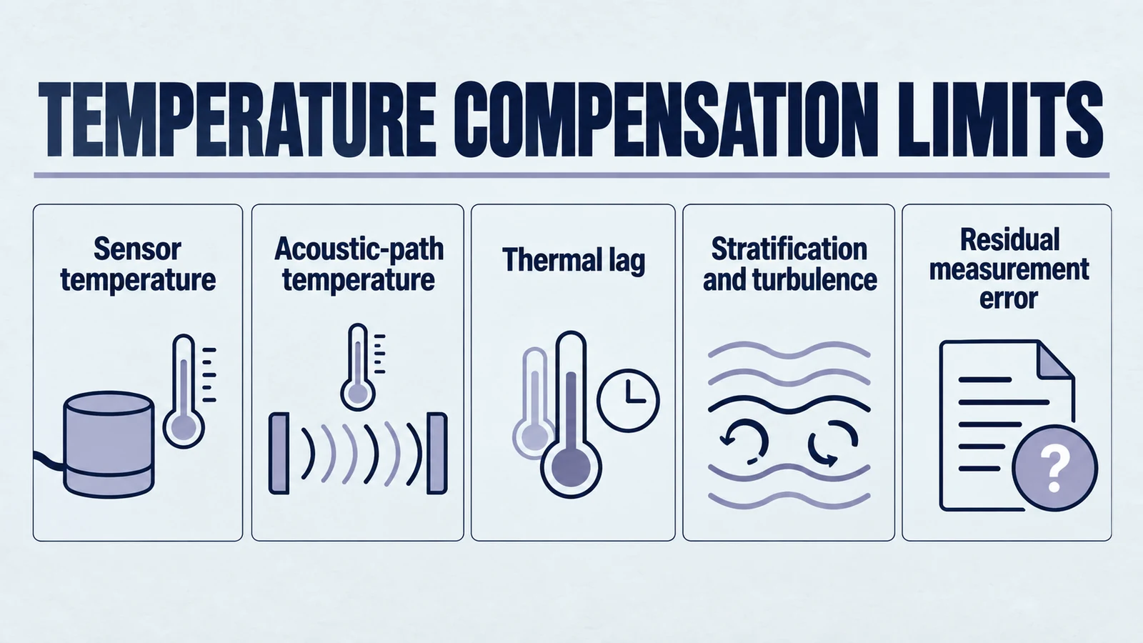
Thermodynamic Foundations of Acoustic Propagation in Industrial Environments
The reliability of ultrasonic distance and level sensing is intrinsically linked to the stability of the medium through which the acoustic energy propagates. In the vast majority of industrial applications, this medium is atmospheric air—a complex, dynamic gas mixture whose physical properties are governed by the laws of thermodynamics. For automation engineers tasked with deploying these systems in outdoor tanks, high-temperature chemical reactors, or thermally unstable manufacturing environments, understanding the relationship between temperature and the speed of sound is the first step in establishing a realistic accuracy framework.
Ultrasonic sensors function by emitting a burst of high-frequency sound waves and measuring the time elapsed until the reflected echo is received by the transducer. This time-of-flight (ToF) is converted to distance using the fundamental equation , where represents the distance to the target, is the velocity of sound, and is the round-trip travel time. The critical vulnerability in this calculation is the assumption that remains constant.
In an ideal gas, the velocity of sound is defined by the Laplace-Newton equation:
Product path for this search intent
Match the article topic to the right YJ Piezo product page
Use this article when the choice is not just a shape, but a material tradeoff between sensitivity, loss, coupling, stability, and operating field. For "Temperature Drift in Ultrasonic Sensing: Causes and Mitigation Limits", the practical value is in turning the topic into a measurable selection or sourcing decision.
- PZT Material Hub
Material grades and application tradeoffs
- Piezoelectric Ceramics
Shapes and ceramic manufacturing options
- PZT Material Supplier Hub
Material control, grade selection, and sourcing support
In this expression, represents the adiabatic index or ratio of specific heats (approximately for dry air), is the universal gas constant (), is the absolute temperature in Kelvin, and is the mean molecular mass of the gas. This relationship demonstrates that the speed of sound is proportional to the square root of the absolute temperature. As thermal energy is added to the system, the kinetic energy of the air molecules increases, allowing them to vibrate and transmit acoustic pressure waves more rapidly.
For practical engineering purposes within a limited temperature range near , a linear approximation is frequently used:
This indicates that for every increase in temperature, the speed of sound increases by approximately . While a change of appears minor relative to a baseline of at room temperature, its impact on measurement accuracy is profound. A temperature shift—common between dawn and midday in many outdoor installations—results in a change in velocity, translating to a error in the reported distance.
| Temperature (∘C) | Speed of Sound (v, m/s) | Density of Air (ρ, kg/m) | Time of Flight per Meter (2d/v, ms) |
|---|---|---|---|
| -25 | 315.7 | 1.4224 | 6.33 |
| -15 | 322.0 | 1.3673 | 6.21 |
| -5 | 328.25 | 1.3163 | 6.09 |
| 5 | 334.32 | 1.2690 | 5.98 |
| 15 | 340.27 | 1.2250 | 5.88 |
| 25 | 346.13 | 1.1839 | 5.78 |
| 35 | 351.88 | 1.1455 | 5.68 |
Using this table’s 334.32 m/s at 5°C as a fixed conversion reference for a 10 m uniform path actually at 35°C and 351.88 m/s gives 10×334.32/351.88 ≈ 9.501 m: about 0.499 m low. State the calibration reference and path conditions when estimating thermal error; compensation can reduce a uniform-path error but not automatically an unmeasured gradient.
Beyond temperature, the molecular mass of the air is influenced by humidity. As the amount of water vapor increases, it replaces heavier nitrogen and oxygen molecules with lighter molecules ( vs. for air). This decrease in mean molecular mass leads to an increase in sound velocity, though the effect is significantly smaller than that of temperature. At , the shift from to relative humidity accounts for only a change in measurement. However, at elevated temperatures (), the saturation pressure of water vapor rises exponentially, making humidity compensation more critical for high-precision applications.
Piezoelectric Material Stability and Transducer Impedance Shifts
The transducer itself—the interface between the electronic system and the physical environment—is not immune to thermal effects. Most industrial ultrasonic sensors utilize Lead Zirconate Titanate (PZT) ceramics, such as those manufactured by Yujie Piezo, due to their high piezoelectric coefficients and mechanical robustness. The performance of these materials is highly temperature-dependent, as the dielectric constant, elastic modulus, and piezoelectric charge coefficients () all shift with thermal energy.
| PZT Grade | Type | Primary Industrial Use | Curie Temp (Tc) | Thermal Stability |
|---|---|---|---|---|
| PZT-4 | Hard | High-power cleaning, Sonar | Moderate | |
| PZT-5A | Soft | Level sensing, Flaw detection | Excellent | |
| PZT-5H | Soft | Medical imaging, Precision | Poor (sensitive) | |
| PZT-8 | Hard | Ultrasonic welding, Bonding | Very High |
For industrial sensing, PZT-5A is the industry standard because it maintains relatively stable sensitivity across a wide temperature window. However, as the temperature rises toward the material's Curie point—the temperature at which it loses its piezoelectric properties—the transducer's resonant frequency () and parallel frequency () shift. Experimental data indicates that for a PZT transducer, the parallel frequency can shift by approximately . Furthermore, the electrical impedance signature of the transducer broadens and its amplitude decreases as temperature increases.
A significant consequence of this material shift is the change in the transducer's capacitance. For instance, increasing the temperature from to can increase the capacitance of a PZT element by over . This creates an impedance mismatch between the sensor and its driving circuitry, potentially leading to a reduction in signal-to-noise ratio (SNR) and a loss of echo strength. In extreme cases, if the transducer is exposed to temperatures exceeding half its Curie point for prolonged periods, irreversible depolarization can occur, permanently degrading the sensor's sensitivity. For high-temperature non-destructive testing (NDT) or logging in deep-well environments (), specialized materials like bismuth titanate or lithium niobate are required to prevent sensor failure.
The Internal Temperature Sensor vs. Ambient Air Mismatch
The most common mitigation technique in industrial ultrasonic sensors is the integration of an internal temperature sensor, such as an NTC thermistor or a digital IC sensor, within the transducer housing. The sensor's firmware uses the reading from this internal probe to adjust the sound velocity constant used in distance calculations. While this approach is effective for steady-state conditions, it introduces several significant error sources in dynamic environments.
Thermal Lag and Housing Inertia
Ultrasonic sensors are typically encased in robust stainless steel, PVC, or plastic housings, often filled with epoxy potting for environmental protection. This mass creates thermal inertia, defined by the thermal time constant—the time required for the sensor to reach of a step-change in ambient temperature. In an outdoor installation, the air temperature can rise rapidly as the sun comes up, but the internal thermistor, shielded by the housing mass, may lag behind the actual air temperature by to minutes. During this lag period, the sensor applies an incorrect compensation factor, leading to a temporary but significant measurement drift.
Sensor Self-Heating
As an active electronic device, an ultrasonic sensor generates its own heat during operation. A standard sensor might dissipate of power. In applications where the sensor is mounted in a confined space with poor airflow, this self-heating can raise the internal temperature of the sensor by to above the actual ambient air. If the compensation algorithm uses this elevated internal temperature, it will assume the sound is traveling faster than it actually is, causing the sensor to report a distance longer than reality for a fixed measured flight time (and a lower level in a top-down H−d calculation). This is particularly problematic in precision tasks like liquid volume measurement, where a error can result in a volume deviation of several gallons in a large tank.
Local Point Measurement vs. Path Average
Perhaps the most fundamental limitation of internal compensation is that it measures the temperature at a single point—the sensor face. In real industrial installations, the temperature is rarely uniform throughout the entire measurement path. A sensor mounted on the roof of a silo might detect a temperature of due to solar heating of the metal roof, while the air near the grain surface meters below is only . Using the sensor's face temperature for the entire path compensation leads to a systematic overestimation of the sound speed.
Advanced Compensation: Reference Targets and Their Constraints
To overcome the limitations of point-based internal sensing, high-precision industrial systems often utilize Reference Target Temperature Compensation (RTTC). This method employs a mechanical reference target—a small, fixed reflector such as a metal pin or bar—mounted at a known, precise distance from the transducer face.
The sensor's operational cycle for RTTC is as follows:
- The sensor emits a pulse and measures the time-of-flight to the fixed reference target ().
- Since the distance to the reference target () is a known constant, the actual speed of sound () in the immediate vicinity is calculated: .
- This "calibrated" speed of sound is then used to determine the distance to the primary target ().
RTTC is exceptionally effective at eliminating errors from self-heating, thermal lag of the housing, and even changes in air composition or humidity, as it measures the actual acoustic velocity in the current environment. It is the preferred solution for outdoor canal level monitoring and large-scale bulk storage. However, RTTC is not a universal panacea and faces its own set of unavoidable physical limits.
The Limits of Path Representative Sampling
The primary constraint of RTTC is the assumption that the air between the transducer and the reference target is representative of the air for the entire measurement distance. If the reference target is located from the sensor, it accurately compensates for the first of the path. If the total measurement range is meters and the air is stratified, the RTTC method will still fail to account for the temperature variations in the remaining meters. In high-moisture tanks where condensation forms, water droplets on the reference target can also distort the calibration, potentially leading to false readings or signal loss.
| Compensation Method | Primary Benefit | Main Weakness | Suitable Environment |
|---|---|---|---|
| Internal NTC | Low cost, simple | Thermal lag, self-heating | Stable, indoor climate |
| External RTD/IC | No self-heating error | Still has lag, point-only | Outdoor sheltered |
| Reference Target | Real-time measurement | Stratification blind spots | High precision, uniform |
| Multi-point Sensors | Path profiling | Wiring complexity, cost | Critical process, stratified |
Unavoidable Limitations: Thermal Stratification and Turbulence
In many industrial scenarios, the environment is so complex that standard compensation algorithms reach their mathematical and physical limits. For automation engineers, identifying these "uncompensatable" zones is crucial for risk management.
Thermal Stratification in Enclosed Volumes
Thermal stratification is a phenomenon where air layers of different temperatures form due to gravity and lack of mixing. In a large fuel tank, the air near the top is heated by the sun, while the fuel itself acts as a massive heat sink, cooling the air layer directly above the liquid surface. This results in a non-linear temperature gradient. Because the speed of sound is a function of the local temperature at every point along the path, the total travel time is the integral of the reciprocal velocity:
Where is the temperature-dependent velocity at height . Since a standard ultrasonic sensor only has access to one or two data points (the face temperature and perhaps a reference target), it cannot solve this integral accurately. The resulting error in stratified tanks typically ranges from to of the distance, even with "active" compensation enabled.
Acoustic Refraction and Bending
In addition to timing errors, temperature gradients can cause the sound beam to physically bend, a phenomenon known as refraction. According to Snell's Law, when a sound wave passes through layers of different densities (temperatures), it refracts toward the region of lower velocity (cooler air). In long-distance horizontal sensing or large-diameter pipelines, a significant vertical temperature gradient can "bend" the acoustic cone away from the target or the receiver, leading to a complete loss of signal. This is particularly common in gas pipelines with low flow rates, where the pipe walls are significantly warmer or cooler than the gas, creating a "lens" effect that distorts the sound path.
Atmospheric Turbulence and Signal Jitter
In outdoor environments, wind and thermal plumes do not just change the average temperature; they create turbulence. Turbulent eddies—organized coherent structures of air movement—cause random, high-frequency fluctuations in both the amplitude and phase of the traveling sound wave. This "phase noise" appears as jitter in the distance measurement.
High-intensity turbulence can lead to:
- Signal Fading: Destructive interference from scattered sound waves reduces the received echo strength.
- Phase Inversion: Rapid changes in air density shift the wave's phase, confusing zero-crossing detection algorithms.
- Path Deflection: Strong cross-winds (above ) can physically displace the sound cone, making it miss the receiving transducer entirely.
While digital filters like median or averaging filters can smooth out some of this jitter, they do so at the cost of response time. If the turbulence is severe enough, the signal-to-noise ratio drops below the detection threshold, and the sensor will report a "lost echo" or a maximum-distance error.
Real-World Drift Patterns and Case Studies
To provide a realistic expectation framework, it is useful to examine how these theoretical limits manifest in actual industrial installations.
Case Study: Outdoor Liquid Level Monitoring
In a study of an urban stream monitoring system, both an ultrasonic sensor and a pressure transducer were used to measure water stage. While the pressure transducer remained stable, the ultrasonic measurements exhibited clear diurnal cycles directly correlated with air temperature. During the hot afternoon, the ultrasonic sensor consistently reported a higher water level (shorter distance) than the pressure transducer, even with temperature compensation enabled. This was attributed to the "thermal lag" of the sensor housing and the presence of a temperature gradient between the sensor and the water surface. The percentage deviation between the two sensors reached up to , highlighting the limits of non-contact sensing in unshielded outdoor environments.
Case Study: High-Temperature Pipeline NDT
In the petrochemical industry, ultrasonic transducers are used to monitor the remaining wall thickness of high-temperature pipes () in real-time. The "drift" in this context is not just an error in measurement, but a threat to the sensor itself. Standard transducers will suffer permanent damage above due to internal disbonding from thermal expansion. High-temperature designs must use specialized delay lines—buffers that insulate the piezoelectric element from the hot surface. Even with these buffers, the duty cycle is limited; a sensor can only be in contact with a surface for to seconds before it must be air-cooled for a full minute. The temperature drift in the material being measured also changes its sound velocity (approximately for steel), requiring a dynamic calibration that tracks the pipe's temperature to maintain sub-millimeter accuracy.
Case Study: Agricultural Irrigation Channels
Research into low-cost ultrasonic sensors (like the HC-SR04 and JSN-SR04T) used for irrigation flumes demonstrated that uncalibrated and uncompensated sensors were entirely unreliable for discharge quantification. Without compensation, the mean absolute deviation (MAD) was over on a range. With temperature compensation and field calibration, the error was reduced to (). This highlights that for short-range, well-ventilated outdoor applications, basic compensation can be highly effective, but it requires field-level calibration to account for local installation variables.
Engineering Framework: Setting Realistic Accuracy Expectations
For an automation engineer, the "mm accuracy" often cited in sensor datasheets is a laboratory specification that rarely translates to the field without significant mitigation. The following table provides an engineering rubric for expected accuracy across different environmental conditions.
| Environmental Category | Typical Temp Stability | Expected Absolute Accuracy | Primary Accuracy Driver | Recommended Technology |
|---|---|---|---|---|
| Controlled Indoor | Sensor resolution | Internal Compensation | ||
| Industrial Factory | Local drafts/air currents | Internal Comp + Filtering | ||
| Outdoor Sheltered | Diurnal cycles/thermal lag | RTTC or External Probe | ||
| Outdoor Sun-Exposed | Radiative heating/Lag | Sun Shield + RTTC | ||
| Stratified Tank | Variable | Non-linear temp gradient | Stilling Well + RTTC | |
| Turbulent/High-Flow | Chaotic | (or signal loss) | Path deflection/Scattering | Low Freq + Averaging |
Best Practices for Mitigation
To maximize the performance of Yujie Piezo sensors or any high-quality industrial ultrasonic system, engineers should follow a tiered mitigation strategy:
- Physical Shielding: Always use a radiation shield for outdoor sensors to prevent the sun from heating the housing above the ambient air temperature.
- Thermal Decoupling: When mounting on hot tanks or pipes, use non-conductive mounting brackets to prevent heat transfer to the sensor body.
- Reference Targets: In critical level applications, utilize a sensor with a reference target to bypass the errors introduced by thermal lag and self-heating.
- Air Normalization: If measuring in a highly stratified tank, consider using a stilling well or a small fan to normalize the air column temperature.
- Averaging and Filtering: Use software-side median filtering to reject the stochastic "jitter" caused by air turbulence, especially at distances greater than meters.
- Field Calibration: Perform a "hot" and "cold" calibration during commissioning. Use a manual tape measure to verify the sensor's reported distance at both ends of your expected temperature window.
Conclusion: Balancing Physics and Pragmatism
Temperature drift in ultrasonic sensing is not a flaw of the sensor; it is an unavoidable consequence of the physics of acoustic propagation in a compressible medium. While modern sensors from leading manufacturers like Yujie Piezo integrate sophisticated compensation algorithms, they are essentially solving a one-dimensional problem in a three-dimensional, dynamic world.
The "mitigation limit" is reached when the environment becomes non-uniform—through stratification, turbulence, or extreme gradients—making it impossible for a single-point sensor to accurately profile the entire measurement path. By understanding these limits and setting a realistic expectation framework (typically to absolute accuracy for industrial field conditions), engineers can design more robust automation systems that account for environmental uncertainty rather than being surprised by it. Ultrasonic sensing remains the most cost-effective and reliable method for non-contact measurement in a wide range of industries, provided the physics of the medium are respected and the limitations of compensation are understood.
Related Technical Resources
Use these internal references to compare geometry, material selection, reliability testing, and sourcing decisions.
- How Bowl-Shaped Piezo Ceramics Focus Ultrasound
- Spherical Cap vs Hemispherical Piezo Ceramics
- When Not to Use Focused Piezoelectric Ceramics
- How to Choose Radius of Curvature for Focused Piezo Ceramics
- Key Design Parameters for Curved Piezo Elements
- Focused Piezo Ceramics in Medical Ultrasound: Engineering Constraints
- Mode Coupling Risk in Piezo Ceramic Geometry
- Selecting Piezo Ceramics for Continuous Duty Applications
Engineering decision notes
PZT material and ceramic selection
Use this article when the choice is not just a shape, but a material tradeoff between sensitivity, loss, coupling, stability, and operating field. For "Temperature Drift in Ultrasonic Sensing: Causes and Mitigation Limits", the practical value is in turning the topic into a measurable selection or sourcing decision.
YJ Piezo coordinates PZT ceramic projects with manufacturing support, so material formulation, sintering, polarization, electrode process, and outgoing inspection can be reviewed against the final application.
Selection checks
- Separate sensing needs from high-power actuation needs before comparing d33 or coupling values.
- Check dielectric loss, Qm, Curie temperature, aging behavior, and operating field against the real duty cycle.
- Confirm whether the application needs standard PZT grades or a custom formulation and geometry.
Failure risks
- Choosing only the highest d33 can create heat, drift, or depolarization risk in power ultrasonics.
- A ceramic that performs well in free measurement can fail once bonded, clamped, or loaded.
- Material substitutions without batch testing can change capacitance, resonance, and system tuning.
RFQ details
- Is the part used for sensing, actuation, atomization, cleaning, welding, or measurement?
- What field strength, temperature, duty cycle, and mechanical load will the ceramic see?
- Which values must be controlled: d33, capacitance, resonance, impedance, Qm, or dimensional tolerance?
Relevant YJ Piezo pages
- PZT Material Hub
Material grades and application tradeoffs
- Piezoelectric Ceramics
Shapes and ceramic manufacturing options
- PZT Material Supplier Hub
Material control, grade selection, and sourcing support
Application FAQ
- Is the highest d33 always the best PZT choice?
- No. High d33 can be useful for sensitivity, but high-power ultrasonic systems often need lower loss, higher Qm, better thermal stability, and safer operation under field and stress.
- What makes PZT material selection different from catalog buying?
- The right PZT choice depends on geometry, load, drive field, duty cycle, temperature, and inspection targets. A catalog value is only useful when it is tied to the final assembly conditions.