
Troubleshooting Sensor Drift: The Role of Temperature Compensation in Precision Ultrasonic Monitoring
1. Introduction: The Invisible Variable in Industrial Metrology
In industrial automation and environmental monitoring, accurate liquid-level measurement supports efficiency, process control, and inventory management. Among the technologies available for this task—ranging from hydrostatic pressure sensors to guided wave radar—ultrasonic level sensors are widely used because they are non-contact, mechanically simple, and cost-effective in suitable applications. However, ultrasonic measurement depends on the physical medium of measurement: the atmosphere itself.
Unlike radar, which propagates at the speed of light largely independent of the air’s properties, ultrasonic sensors rely on mechanical pressure waves traveling through gases. This reliance makes them inherently susceptible to the capricious nature of environmental conditions. As industries increasingly deploy autonomous monitoring solutions—exemplified by products like the UltraNova and SR series from Yujie Piezo Technology—in outdoor and unconditioned environments, the challenge of "sensor drift" has emerged as a critical technical hurdle.
Sensor drift, in the context of ultrasonic measurement, is often related to the dynamic thermodynamic properties of the air column through which the sound travels. A sensor calibrated at 9:00 AM may report an error of several centimeters by 2:00 PM, not because the liquid has moved, but because the sun has warmed the air and changed the velocity of the acoustic pulse. In applications such as chemical storage or sewage-level monitoring, these errors can contribute to false alarms, inventory discrepancies, or compliance-related investigation.
Product path for this search intent
Match the article topic to the right YJ Piezo product page
Use this article when sensor performance depends on target distance, beam angle, housing material, liquid behavior, or false echo control. For "Troubleshooting Sensor Drift: The Role of Temperature Compensation in Precision Ultraso...", the practical value is in turning the topic into a measurable selection or sourcing decision.
- Ultrasonic Sensors
Distance, level, and detection sensor portfolio
- Flow Measurement Transducers
Bubble and flow-related ultrasonic sensing paths
- Air Acoustic Transducers
Air-coupled transducers for range and presence detection
This technical guide explains the mechanisms behind temperature-induced sensor drift and the engineering solutions designed to mitigate it. It covers sound propagation, diurnal temperature cycles, and the role of internal temperature compensation algorithms. It also examines how sensing platforms—specifically the UltraNova1, UltraNova2, and SR55 sensors—combine hardware materials like PVDF and IP68 housings with onboard processing to support millimeter-level measurement under specified conditions.
2. The Physics of Ultrasound and Atmospheric Propagation
To truly troubleshoot and prevent sensor drift, one must first possess a nuanced understanding of the underlying physics that govern ultrasonic measurement. The ultrasonic sensor is, fundamentally, a timing device. It does not measure distance directly; it measures the Time-of-Flight (ToF) of a sound pulse and infers distance based on an assumed speed of sound. The fidelity of this inference is entirely dependent on the accuracy of that speed value.
2.1 The Mechanics of Longitudinal Waves
Ultrasonic waves are longitudinal compression waves. When a piezoelectric transducer—such as those manufactured by Yujie Piezo—is excited by an electrical signal, it vibrates, compressing and rarefying the air molecules immediately adjacent to its face. This disturbance propagates through the air as kinetic energy is transferred between colliding molecules.
The velocity of this propagation is not a universal constant like the speed of light in a vacuum. Instead, it is a property of the material medium. In gases, the speed of sound () is governed by the stiffness of the gas (how much it resists compression) and its density (how heavy the molecules are). The governing equation from classical thermodynamics is the Newton-Laplace formula:
Where:
- is the isentropic bulk modulus (stiffness).
- (rho) is the density of the gas.
While this equation is fundamental, it is often more useful in engineering contexts to express it in terms of temperature, as temperature is the primary variable that shifts in outdoor environments. Using the Ideal Gas Law (), we can substitute density and pressure to arrive at the temperature-dependent form:
Where:
- (gamma) is the adiabatic index (approximately 1.402 for dry air).
- is the universal gas constant (8.314 J/mol·K).
- is the absolute temperature in Kelvin.
- is the molar mass of the gas (0.02896 kg/mol for dry air).
2.2 The Dominance of Temperature
The equation reveals the critical insight that drives the need for compensation: The speed of sound is proportional to the square root of the absolute temperature.
As the air temperature () rises, the gas molecules possess higher kinetic energy. They move faster and collide more frequently, transmitting the acoustic vibrational energy more rapidly. Conversely, as the temperature drops, molecular motion slows, and the speed of sound decreases.
For practical implementation in sensor microcontrollers, such as those inside the UltraNova series, this square-root relationship is often approximated by a linear Taylor series expansion valid over the typical range of Earth's atmospheric conditions. The standard engineering formula used is:
Where:
- 331.3 m/s is the speed of sound at 0°C.
- T is the ambient temperature in degrees Celsius.
- 0.606 is the temperature coefficient.
This coefficient indicates that for every single degree Celsius rise in temperature, the speed of sound increases by roughly 60 centimeters per second. While this may appear negligible, integrated over the travel time of a pulse across a 4-meter tank (the operational range of the UltraNova1 and SR55), it accumulates into significant linear errors.
2.3 Secondary Environmental Factors: Humidity and Pressure
While temperature is the protagonist in the story of sensor drift, humidity and pressure are important supporting characters.
- Humidity: The presence of water vapor in the air affects the molar mass (M) of the gas mixture. Water molecules (H₂O, molar mass ~18 g/mol) are lighter than Nitrogen (N₂, ~28 g/mol) or Oxygen (O₂, ~32 g/mol). Therefore, humid air is less dense than dry air. According to the Newton-Laplace equation, lower density (ρ) leads to a higher speed of sound (c). In extremely humid environments—such as the headspace of a sewage lift station where the SR55 might operate—the speed of sound is slightly faster than in dry air at the same temperature. However, the maximum error introduced by 100% relative humidity is typically less than 0.5% at standard temperatures, making it a lower priority for compensation than temperature, though high-end algorithms may account for it.
- Atmospheric Pressure: In an ideal gas, pressure changes result in proportional density changes, canceling each other out in the speed of sound equation. Thus, for standard outdoor monitoring (at varying altitudes or weather fronts), pressure has a negligible effect on the speed of sound. It does, however, affect the attenuation (signal strength) of the sound, but not the timing, which is the variable of interest for drift.
2.4 The Mathematics of Error
To quantify the necessity of the internal temperature compensation featured in Yujie's sensors, consider a hypothetical uncompensated measurement.
Scenario: A Mid Range sensor (like the SR55) is mounted 4 meters above a target.
- Calibration: The sensor is calibrated at 20°C, assuming v = 343.4 m/s.
- Event: A cold front moves in at night, dropping the temperature to 0°C.
- Physics: At 0°C, the actual speed of sound is 331.3 m/s.
- Measurement: The sound pulse travels 4m down and 4m up (8m total).
- True Time of Flight (ToF) = 8m / 331.3 m/s = 0.024147 seconds.
- The Error: The uncompensated sensor measures 0.024147s. It multiplies this by its hardcoded speed of 343.4 m/s.
- Calculated Distance = (0.024147s × 343.4 m/s) / 2 = 4.146 meters.
Result: The sensor reports the distance is 4.146 meters. The actual distance is 4.000 meters. The sensor has drifted by 14.6 cm. In a chemical inventory system using the UltraNova1, that error could create a meaningful inventory discrepancy or false alarm. This mathematical example shows why tight measurement accuracy is difficult to maintain without temperature compensation matched to the installation.
3. The Anatomy of Drift: Diurnal Cycles and Outdoor Dynamics
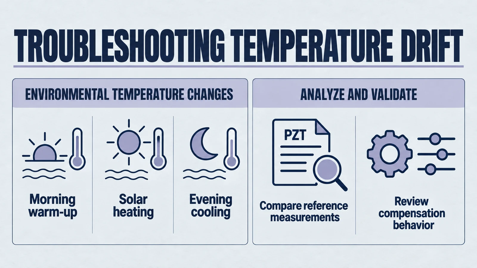
Sensor drift is most aggressively manifested in outdoor environments subject to the diurnal (day/night) temperature cycle. Understanding the specific phases of this cycle helps in diagnosing when and why measurement errors occur.
3.1 The Morning Transition (Dew and Rapid Warming)
As the sun rises, the ambient air temperature can increase rapidly—sometimes by 5-10°C per hour in arid regions. This period poses two distinct challenges:
- Thermal Lag: The air warms up faster than the sensor body. The sensor's housing has thermal mass (inertia). If the sensor relies on measuring its own body temperature to estimate air temperature, there will be a lag. The air might be 25°C, but the sensor body is still at 15°C. The compensation algorithm will use the lower temperature, resulting in an underestimation of the speed of sound.
- Condensation: In the early morning, the sensor face may be colder than the dew point of the surrounding air, leading to condensation. Water droplets on the face of an UltraNova2 can act as acoustic dampeners or phantom targets, causing unstable readings. The IP68 rating of the UltraNova and SR55 series helps protect the electronics from moisture ingress, while the external face still needs installation and maintenance practices appropriate for the environment.
3.2 Peak Solar Loading (The "Oven" Effect)
Mid-day presents the most severe drift scenario: Solar Loading. When a sensor is exposed to direct sunlight, the housing absorbs solar radiation. The internal temperature of the sensor can rise significantly above the ambient air temperature.
- The Discrepancy: The air temperature (path temperature) might be 30°C. The sensor internal temperature (measured by the thermistor) might bake up to 50°C.
- The Consequence: If conversion uses 361 m/s while the actual uniform path speed is 349 m/s, indicated distance is 361/349 ≈ 1.0344 times the true distance, about 3.44% longer. A top-down level computed as reference height minus distance therefore appears lower. The actual error depends on the acoustic path and compensation algorithm.
- Mitigation in Design: This is where material selection becomes a functional drift-mitigation feature. The UltraNova1 utilizes a PVDF (Polyvinylidene Fluoride) housing. PVDF is naturally opaque and UV resistant. Compared to black ABS plastics often used in cheaper sensors, PVDF can reduce the solar heat gain, keeping the internal thermistor closer to the true ambient temperature.
3.3 The Evening Cooling (Stratification)
As the sun sets, the ground and the tank structure cool down. However, the air inside a tank may remain warm, or stratify into layers.
- Stratification: Hot air rises. In a 4-meter tall tank (the range of the UltraNova1), the air at the top (near the sensor) might be 20°C, while the air near the liquid surface is 10°C.
- The Averaging Problem: The ultrasonic pulse travels through both layers. The total time of flight depends on the average temperature of the column. Internal compensation typically measures temperature at the sensor face (the top). In this evening scenario, the sensor might overestimate the average temperature, leading to a drift error. However, this is generally less severe than the solar loading error.
4. Internal Temperature Compensation: The Technological Solution
To counteract the physics of gas thermodynamics and the vagaries of weather, modern sensors like the Yujie UltraNova and SR series employ integrated "Internal Temperature Compensation." This is a fusion of hardware sensing and software algorithmic processing.
4.1 Hardware: The Embedded Thermistor
The heart of the compensation system is a temperature transducer—typically a high-precision Negative Temperature Coefficient (NTC) thermistor or a digital bandgap temperature sensor—embedded within the sensor housing.
- Proximity: For the UltraNova1 and SR55, the goal is to place this thermistor as close to the transducer face as possible without interfering with the acoustic path. The face is the interface with the world; measuring the temperature at the face provides the best proxy for the air temperature immediately entering the measurement zone.
- Thermal Coupling: The thermistor must be thermally coupled to the environment but thermally isolated from the sensor's own self-heating (generated by the microcontroller and the high-voltage transmit circuit). Advanced potting materials and housing designs in the UltraNova series help achieve this balance, ensuring the reported temperature reflects the environment, not the circuit board.
4.2 The Algorithmic Loop
The UltraNova and SR55 sensors do not simply "read" distance. They compute it through a continuous feedback loop. The firmware operation can be visualized as follows:
- Wake & Sense: The sensor wakes up (crucial for "Battery Powered Capable" units like UltraNova1/2).
- Read Temperature (T): The ADC (Analog-to-Digital Converter) samples the voltage across the internal thermistor.
- Compute V_sound: The processor applies the compensation polynomial: .
- Pulse & Time: The ultrasonic burst is fired, and the echo return time (ToF) is captured with microsecond precision.
- Calculate Distance: .
- Filter & Output: The result is passed through smoothing filters to reject transient noise before being output via Analog (4-20mA in the SR55) or digital protocols.
This process happens in milliseconds. By recalculating v(T) for every single measurement, the sensor effectively "neutralizes" the temperature variable. A UltraNova2 measuring a machine part at 1000mm will read 1000mm whether the machine is cold at startup or hot after running for hours, provided the air gap temperature is tracked by the sensor.
4.3 "Millimeter-Level Accuracy"
Yujie's documentation describes these sensors as supporting "millimeter-level" resolution or accuracy under specified conditions. In a 4000mm range (4 meters), 1mm resolution represents 1 part in 4000 (0.025%). While the resolution might be 1mm, the absolute accuracy in the field still depends on compensation, target geometry, air-path stability, and installation. Temperature compensation can reduce error from ambient swings, but the final accuracy claim should be verified in the customer's own measurement setup.
5. Product Deep Dive: Yujie's Solutions for Variable Environments
The theoretical principles of drift and compensation are applied differently across Yujie’s product portfolio. Each sensor series—UltraNova1, UltraNova2, and SR55—is engineered with specific attributes to combat environmental instability in its target application.
5.1 UltraNova1: The Chemical Processing Specialist
- Target Application: Chemical tanks, waste bins, 2-4 meter vessels.
- The Drift Challenge: Chemical tanks are often located outdoors in tank farms, exposed to full sun and weather. Furthermore, the vapor inside the tank (e.g., acid fumes) may have different thermal properties than standard air.
- The Yujie Solution:
- PVDF Housing: The UltraNova1 is constructed with a PVDF (Polyvinylidene Fluoride) housing. While primarily selected for its exceptional resistance to strong acids, solvents, and oxidants, PVDF plays a subtle but vital role in drift prevention. Corrosion on a sensor face alters its acoustic impedance and roughness. A corroded face scatters sound, leading to a weak echo. A weak echo is difficult to time-stamp accurately—the "rising edge" of the return pulse becomes blurry. This timing uncertainty manifests as "jitter" or high-frequency drift. By remaining chemically inert, the PVDF housing ensures the acoustic interface remains pristine, allowing the internal compensation algorithm to work with clean, sharp signals.
- Mid-Range Capability (4m): At 4 meters, the air volume is large enough that temperature gradients can form. The internal compensation is tuned to average these effects over the mid-range distance.
- Battery Powered Capable: This sensor is capable of battery operation with low power consumption. This is critical for remote chemical bins where no grid power exists. The drift management here involves fast thermal settling times, ensuring the sensor doesn't report erroneous data while "waking up" from a sleep state.
5.2 UltraNova2: The Precision Automation Expert
- Target Application: Machine parts, fluid dispensers, small tanks, short-range high-precision tasks.
- The Drift Challenge: In short-range applications (max 1000 mm), the margin for error is vanishingly small. A 5mm drift, which might be acceptable in a sewage well, is a disaster in a fluid dispensing robot.
- The Yujie Solution:
- Minimal Dead Band: The UltraNova2 features "minimal dead bands". The dead band is the blind zone immediately in front of the transducer. By minimizing this, the sensor can be mounted closer to the target. Measuring a shorter column of air inherently reduces the absolute magnitude of temperature drift (since drift is a percentage of distance).
- Surface Mount Design: The surface mount form factor allows the sensor to be integrated tightly into machine chassis. This often provides a more stable thermal environment than a pole-mount, as the machine's thermal mass helps damp rapid air temperature fluctuations.
- High Precision Focus: The algorithm in the UltraNova2 is likely optimized for resolution. Internal compensation here must be extremely fast to account for heat generated by the machinery itself (e.g., a fluid dispenser warming up nearby).
5.3 SR55: The Rugged Outdoor Survivor
- Target Application: Outdoor sewage, water treatment, hazardous gas environments.
- The Drift Challenge: Sewage lift stations are some of the most difficult environments for ultrasonic sensors. They are humid, often contain methane and H₂S, and are subject to massive temperature swings (freezing surface, warm biological activity below).
- The Yujie Solution:
- H₂S Resistance: The SR55 is explicitly noted for resistance to Hydrogen Sulfide (H₂S). H₂S is a corrosive gas that attacks electronics, specifically copper and silver. "Electronic Drift" often occurs when internal components corrode, changing the resistance of the circuitry. This causes the calibration to wander permanently. By sealing the sensor against H₂S (and achieving an IP68 rating), Yujie ensures that the electronics remain stable. The only variable changing is the air temperature, which the internal compensation can handle.
- IP68 Rating: Protection against continuous submersion and high humidity. This prevents moisture ingress drift.
- Analog Output Stability: The SR55 offers Analog Output (4-20mA or 0-10V) and operates on grid power. In long cable runs typical of water treatment plants, the 4-20mA standard is robust against electrical noise, ensuring that the precise, temperature-compensated measurement made by the sensor reaches the control room without degradation.
6. Installation Best Practices for Minimizing Drift
While Yujie’s UltraNova and SR sensors are equipped with sophisticated internal compensation, their performance can be maximized—or compromised—by installation. To achieve the "millimeter-level accuracy" promised, the following best practices should be adhered to.
6.1 The Sunshade Rule
As discussed in Section 3.2, solar loading is the enemy of internal compensation.
- Recommendation: If an UltraNova1 or SR55 is installed outdoors in direct sunlight, a sunshade or weather hood is mandatory. This simple plastic shield prevents direct solar radiation from heating the sensor body above the ambient air temperature. It allows the internal thermistor to measure the shade temperature, which is a far more accurate proxy for the air temperature in the tank.
6.2 Managing Standpipes
Sensors are often mounted on nozzles or standpipes.
- The Risk: A long metal standpipe acts as a heat sink or radiator. In the sun, the air inside the pipe can become superheated. In the winter, it can freeze.
- Optimization: Keep standpipes as short as possible. Use the UltraNova2's "minimal dead band" feature to mount the sensor closer to the tank interior, potentially eliminating the need for a long nozzle. Ensure the nozzle diameter is sufficient to prevent the beam from hitting the sidewalls, which can create multi-path echoes that confuse the timing algorithm.
6.3 Mounting Angle and Stability
- Alignment: Ensure the sensor face is parallel to the liquid surface. Misalignment weakens the echo. A weak echo is more susceptible to "jitter" caused by thermal turbulence in the air.
- Location: Avoid mounting the sensor directly over the fill inlet. Turbulence from incoming liquid creates a chaotic surface and changes the local air temperature (if the incoming liquid is hot/cold). Mount the sensor at a stable location, 1/3 to 1/2 of the radius from the tank wall.
6.4 Handling Condensation
- The Issue: Morning dew.
- The Fix: While the SR55 and UltraNova are IP68 (waterproof), water droplets on the face can still block the acoustic signal. Mounting the sensor with a very slight angle (if permitted by the beam width) or using a peaked rain shield can help shed water. However, the inherent vibration of the piezoelectric element during the transmit pulse is often sufficient to atomize light condensation, a self-cleaning feature of the technology.
7. Comparative Analysis: Why Internal Compensation Wins
Why rely on ultrasonic sensors with internal compensation rather than other technologies?
| Feature | Ultrasonic (Yujie UltraNova/SR) | Radar (Non-Contact) | Hydrostatic Pressure |
|---|---|---|---|
| Temperature Sensitivity | High (Requires Compensation) | Low (EM waves unaffected) | Medium (Liquid density changes) |
| Compensation Method | Internal Thermistor + Algorithm | N/A | Specific Gravity Correction (Manual) |
| Cost | Moderate/Low | High | Moderate |
| Maintenance | Self-Cleaning (Vibration) | Non-Contact | Contact (Fouling/Drift) |
| Chemical Resistance | PVDF Options (UltraNova1) | PTFE/Steel | Diaphragm Compatibility Issues |
| Blind Zone | Minimal (UltraNova Series) | Larger (Typically) | None |
Analysis:
While Radar is immune to air temperature speed-of-sound changes, it is often overkill and cost-prohibitive for simple tank monitoring, especially in distributed IoT networks (e.g., 1,000 waste bins). Hydrostatic pressure sensors drift because the liquid's density changes with temperature (water expands when warm), introducing a different kind of error that is harder to compensate for without a submerged temperature probe.
The Ultrasonic Sensor with Internal Compensation represents the engineering "sweet spot." It offers the non-contact, chemical-resistance benefits of radar at a fraction of the cost. The "weakness" of air temperature sensitivity is effectively neutralized by the internal compensation engines in the UltraNova1, UltraNova2, and SR55, provided they are installed correctly.
8. Troubleshooting Guide: Diagnosing Drift in the Field
When a user suspects drift, follow this diagnostic workflow using the known attributes of Yujie sensors.
Symptom: Level reading varies by 5-10cm throughout the day despite no liquid being added/removed.
- Check the "Phantom" Process: Is the liquid actually expanding? In a large tank, thermal expansion of the liquid can raise the level by centimeters. Verify with a manual tape measure at the hottest and coldest times.
- Check Solar Exposure: Is the sensor black or dark gray? Is it in the sun? Touch the sensor housing. If it is hot to the touch, "Solar Loading" is the culprit. Solution: Install a sunshade.
- Check the "Cold Shock": Did you just fill a cold tank with hot liquid? The sensor body (and internal thermistor) takes time to warm up. The reading will drift until the sensor reaches thermal equilibrium with the new air temperature. Solution: Wait 15-30 minutes for stabilization.
- Verify the Model: Are you using the right sensor?
- For a 1-meter deep fluid dispenser, use the UltraNova2 (High Precision). Using a long-range sensor here might result in poor near-field resolution.
- For a sewage well with gas, use the SR55. Standard sensors might be suffering from H₂S corrosion drift, not temperature drift.
- Check the Dead Band: Is the liquid level within the minimum range (e.g., top 20cm)? Readings inside the dead band are erratic and highly sensitive to temperature. Lower the liquid level or raise the sensor mount.
9. Future Trends: IoT and Distributed Compensation
The specification that the UltraNova series is "Battery Powered Capable" and "IoT Ready" points toward the future of drift elimination: Distributed Data Fusion.
In current systems, the sensor compensates based on its own internal temperature reading. In future IoT ecosystems, an UltraNova sensor connected to a cloud platform via LoRaWAN or NB-IoT could transmit the raw Time-of-Flight and its internal temperature data. The cloud server, possessing local weather station data (hyper-local ambient temp, humidity, pressure), could perform a "Second-Order Compensation."
If the sensor reports an internal temp of 50°C (due to sun) but the local weather API reports 30°C, the cloud algorithm could flag the Solar Loading error and correct the distance calculation post-transmission. This moves the burden of extreme computational compensation from the low-power sensor MCU to the infinite power of the cloud, enabling even higher accuracy for the simple battery-powered hardware.
10. Conclusion
Sensor drift in outdoor level monitoring is an unavoidable consequence of physics. It is the signature of the atmosphere interacting with the acoustic pulse. However, it is a manageable phenomenon. It is not a flaw in the technology, but a variable in the equation—a variable that Yujie Piezo Technology has engineered solutions to solve.
Through the rigorous application of physics-based design, the UltraNova1, UltraNova2, and SR55 sensors transform the volatile medium of air into a reliable ruler.
- The Physics: By acknowledging the √T shift in sound speed, the internal algorithms turn a weakness into a known quantity.
- The Materials: By utilizing PVDF for chemical/thermal stability and IP68 sealing against moisture and H₂S, the hardware ensures that the signal remains clean enough for the algorithms to work.
- The Result: Millimeter-level accuracy that holds true from the chill of the morning dew to the heat of the afternoon sun.
For the industrial operator, the lesson is clear: Accuracy is not just about buying a sensor; it is about selecting a sensor that understands its environment. By choosing internally compensated platforms like the UltraNova and SR series, and installing them with an awareness of thermal dynamics, the "Invisible Variable" of temperature drift is finally made visible, predictable, and irrelevant.
Quick Reference: Yujie Sensor Capabilities
| Model | Range | Key Material/Feature | IP Rating | Primary Application |
|---|---|---|---|---|
| UltraNova1 | Mid Range (4m) | PVDF Housing (Chem Resistant), Minimal Dead Band | IP68 | Chemical Tanks, Waste Bins, Battery/IoT Apps |
| UltraNova2 | Short Range (~1000mm) | Surface Mount, High Precision, Minimal Dead Band | IP68 | Machine Automation, Fluid Dispensers, Small Tanks |
| SR-55 | Mid Range (4m) | H₂S Resistant, Analog Output, Rugged | IP68 | Outdoor Sewage, Water Treatment, Grid Powered |
Engineering decision notes
Ultrasonic sensing and detection
Use this article when sensor performance depends on target distance, beam angle, housing material, liquid behavior, or false echo control. For "Troubleshooting Sensor Drift: The Role of Temperature Compensation in Precision Ultraso...", the practical value is in turning the topic into a measurable selection or sourcing decision.
YJ Piezo treats ultrasonic sensing as an acoustic interface problem: transducer frequency, beam shape, housing, drive electronics, and target environment are reviewed together.
Selection checks
- Define target range, dead zone, beam angle, and mounting geometry before choosing the sensor family.
- Check the medium, target surface, temperature swing, foam, vapor, and side-wall risk.
- Separate detection repeatability from ideal lab accuracy when the sensor will operate in a tank, tube, or moving line.
Failure risks
- A sensor can pass bench distance tests and still fail in tanks with foam, agitation, vapor, or narrow geometry.
- Changing only frequency without reviewing beam angle and mounting can increase false echoes.
- Ignoring housing material or sealing requirements can shorten lifetime in washdown or chemical environments.
RFQ details
- What is the minimum and maximum detection distance?
- Is the target liquid, solid, sheet material, air flow, or a moving object?
- What temperature, humidity, IP rating, and output signal does the system require?
Relevant YJ Piezo pages
- Ultrasonic Sensors
Distance, level, and detection sensor portfolio
- Flow Measurement Transducers
Bubble and flow-related ultrasonic sensing paths
- Air Acoustic Transducers
Air-coupled transducers for range and presence detection
Application FAQ
- What makes an ultrasonic sensor page useful for procurement?
- It should connect range, beam angle, output signal, housing, mounting, and environmental limits to a concrete use case. A model name alone is not enough for reliable supplier comparison.
- Which information speeds up an ultrasonic sensor RFQ?
- Send the target material, distance range, installation geometry, output interface, temperature range, IP rating, and whether the application involves foam, vapor, liquid, or moving objects.