
MDC Double Sheet Detection Sensors Technical Guide for Manufacturing
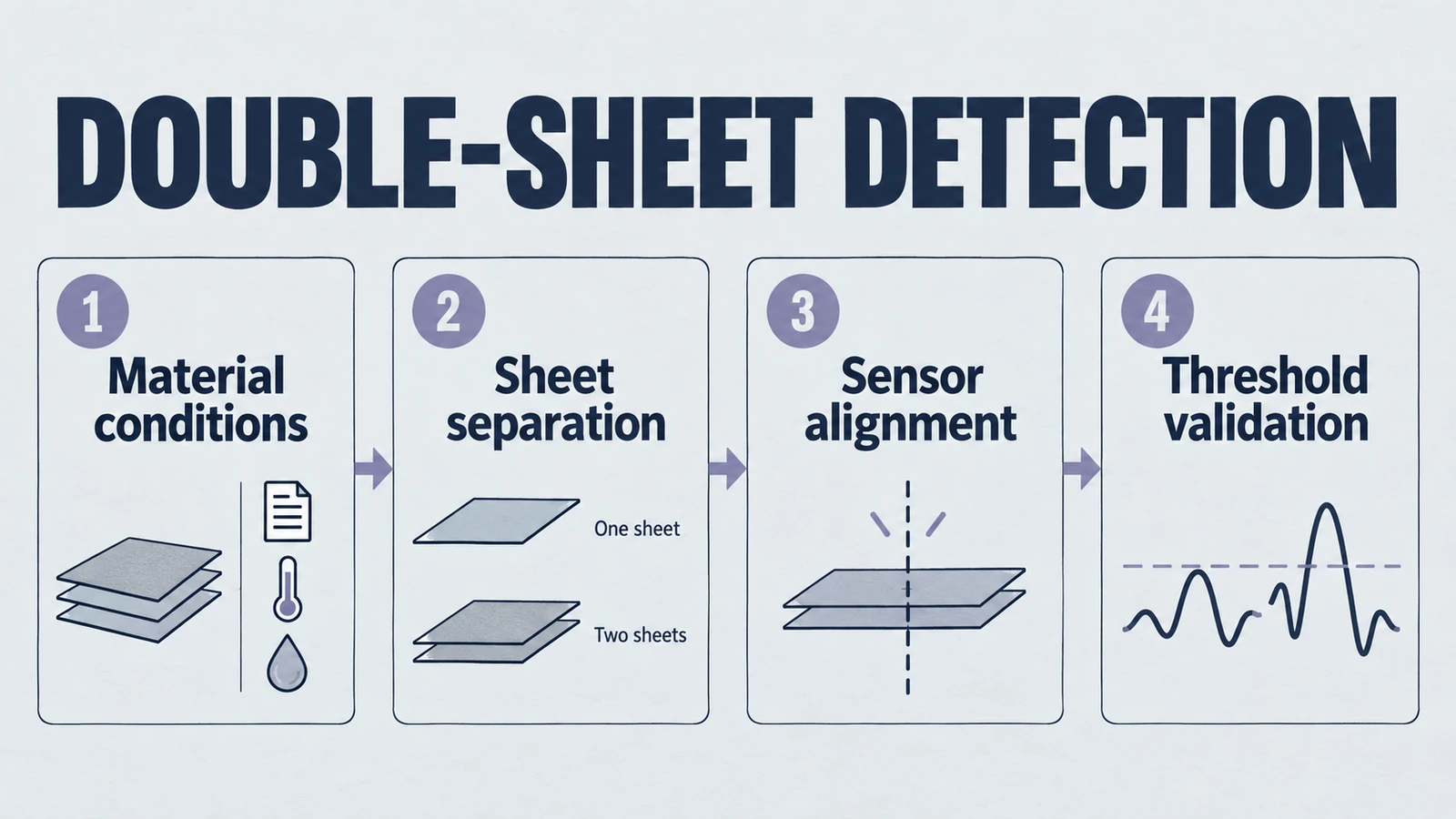
Executive Summary: The Imperative of Absolute Detection
In the contemporary landscape of high-precision industrial manufacturing, the margin for error has effectively vanished. As production lines accelerate to unprecedented speeds—processing thousands of sheets of paper per minute in offset printing or stacking lithium-ion battery electrodes with micron-level precision—the integrity of the material feed becomes the linchpin of operational efficiency. A single error, specifically the inadvertent feeding of two sheets instead of one, represents a severe failure mode. It is not merely a production hiccup; it is a vector for severe machine damage, significant material wastage, and in high-stakes sectors like battery manufacturing, critical safety hazards.
This technical guide for Yujie Piezo explains the MDC Double Sheet Detection Sensor. Positioned at the intersection of material science and signal processing, the MDC sensor uses ultrasonic waves to detect conditions that optical sensors can miss. Unlike capacitive or mechanical alternatives, the MDC sensor uses acoustic impedance differences to discriminate between air, single material layers, and double material layers across many colors, transparency levels, and surface finishes.
Drawing upon Yujie Piezo’s deep expertise in piezoelectric ceramics—the electromechanical heart of every ultrasonic transducer—this report will dissect the operating principles, architectural specifications, and critical industrial applications of the MDC sensor series. We will explore how atomic-level vibrations in a PZT ceramic disc are transformed into robust industrial control signals. Learn more about how shape influences performance in our piezo ceramic geometry guide.
Product path for this search intent
Match the article topic to the right YJ Piezo product page
Use this article when sensor performance depends on target distance, beam angle, housing material, liquid behavior, or false echo control. For "MDC Double Sheet Detection Sensors Technical Guide for Manufacturing", the practical value is in turning the topic into a measurable selection or sourcing decision.
- Ultrasonic Sensors
Distance, level, and detection sensor portfolio
- Flow Measurement Transducers
Bubble and flow-related ultrasonic sensing paths
- Air Acoustic Transducers
Air-coupled transducers for range and presence detection
1. The Physics of Reliability: Ultrasonic Wave Propagation
To understand the engineering superiority of the MDC Double Sheet Detection Sensor, one must first master the underlying physics of ultrasound. Unlike optical sensors that rely on the transmission of photons, or capacitive sensors that measure dielectric permittivity, the MDC sensor relies on the transmission of mechanical energy through matter.
1.1 The Piezoelectric Effect: The Transducer’s Heart
At the core of the Yujie MDC sensor lies a precision-engineered piezoelectric transducer. The term "piezoelectricity" derives from the Greek piezein (to squeeze or press). It describes a phenomenon where specific crystalline materials generate an electrical charge in response to mechanical stress. Conversely, and most critical for the transmitter function of the sensor, these materials exhibit the inverse piezoelectric effect: they undergo physical deformation when an electrical field is applied.
Yujie Piezo utilizes high-grade Lead Zirconate Titanate (PZT) ceramics. When an oscillating voltage—typically in the frequency range of 200 kHz to 400 kHz—is applied to the PZT disc within the MDC transmitter, the crystal lattice expands and contracts at that exact frequency. This microscopic piston-like motion compresses the air molecules in front of the sensor face, generating a longitudinal sound wave that propagates outward.
The quality of this PZT ceramic is paramount. Inconsistencies in the ceramic's density or sintering process would lead to variations in the resonant frequency, causing "blind spots" or weak transmission. Yujie’s vertical integration in manufacturing these ceramic elements ensures that every MDC sensor operates at the optimal electro-acoustic conversion efficiency.
1.2 Acoustic Impedance and the Air Gap Barrier
The fundamental mechanism that allows the MDC sensor to detect a double sheet is the concept of Acoustic Impedance (Z). Acoustic impedance is a measure of the resistance a medium offers to the propagation of a sound wave, defined as:
Where:
- (rho) is the density of the material (kg/m³).
- is the speed of sound in that material (m/s).
The behavior of an ultrasonic wave at the boundary between two materials is governed by the difference in their acoustic impedances.
- Air has extremely low impedance (Z ~ 400 Rayls).
- Solids (paper, metal, plastic) have very high impedance (Z > 1,000,000 Rayls).
When the ultrasonic wave travels from the transmitter (air) to the sheet (solid), a massive impedance mismatch occurs.
- Reflection: The vast majority of the energy is reflected back toward the transmitter.
- Transmission: A small, measurable fraction of the energy couples into the solid sheet, travels through it, and re-emerges into the air on the other side to reach the receiver.
1.2.1 The Physics of the Double Sheet
The "Double Sheet" condition introduces a physical phenomenon that creates a unique acoustic signature. When two sheets are pressed together—even under high roller pressure—a microscopic layer of air remains trapped between them. This creates a multi-layer interface:
Air → Sheet 1 → Trapped Air → Sheet 2 → Air
The sound wave must now negotiate four interfaces in the illustrated air–sheet–air–sheet–air path instead of two.
- The wave enters Sheet 1 (massive reflection).
- The wave tries to exit Sheet 1 and enter the Trapped Air (massive reflection).
- The wave tries to enter Sheet 2 from the Trapped Air (massive reflection).
- The wave exits Sheet 2 to the receiver (massive reflection).
This cascading series of reflections results in a severe attenuation of the signal amplitude. The receiver sees a signal that is drastically weaker than the signal through a single sheet. It is this drastic attenuation caused by the trapped air gap—not the double thickness of the material itself—that the MDC sensor detects. This is why the sensor works equally well on thin foil as it does on thick cardstock; the physics of the air gap remains constant.
1.3 Attenuation vs. Absorption
While impedance mismatch drives reflection, absorption also plays a role. Soft, porous materials like coarse paper or felt absorb ultrasonic energy as heat (due to internal friction of fibers). The MDC sensor’s sophisticated circuitry must distinguish between the absorption of a thick single sheet and the reflection loss of a double sheet. This is achieved through dynamic thresholding and high-energy burst transmission, ensuring that the signal punches through the material while still being sensitive to the interface losses.
2. Architecture of the MDC Double Sheet Sensor
The MDC sensor is not merely a transducer; it is a complete sensing system housed in an industrial-grade enclosure. Based on standard parameters for Yujie Piezo’s class of sensors, the architecture is designed for robust integration into PLC-controlled automation environments.
2.1 Housing and Form Factor
The MDC sensor operates on a through-beam principle, requiring two physically separate units: a Transmitter (Emitter) and a Receiver.
- M18 Cylindrical Housing: The most common form factor, with an 18mm threaded metal barrel. This compact size allows installation in the tight spaces of printing press feeders and gripper arms.
- M30 High-Power Housing: For penetrating thicker materials (like corrugated cardboard or multi-layer packaging), a 30mm diameter housing allows for a larger PZT element. A larger piezo disc generates a higher sound pressure level (SPL), providing the "acoustic punch" needed for difficult materials.
- Angled Heads: Many installations require the sensor to fit in a narrow gap where the cable cannot exit axially. 90-degree angled heads are standard options to accommodate these mechanical constraints.
2.2 Electronic Topography
The internal electronics of the MDC sensor are divided between the transmitter and receiver units.
- Transmitter Electronics: Contains a high-frequency oscillator circuit that drives the PZT element. Advanced models use "chirp" or modulated pulse trains to create a unique sonic signature, preventing cross-talk if multiple sensors are used side-by-side.
- Receiver Electronics: Contains a sensitive amplifier, a band-pass filter (to reject industrial noise like air hiss), and a comparator logic circuit.
- The Evaluation Unit: In some older or ultra-compact designs, the evaluation logic is external. However, the modern MDC sensor integrates the evaluation logic directly into the receiver housing. It analyzes the amplitude of the incoming signal and compares it against stored values from the "Teach-in" process.
2.3 Operating Ranges and Specifications
Based on industry standards for the MDC class:
- Sensing Distance (Gap Width): The optimal distance between transmitter and receiver is typically 20 mm to 60 mm, with 40 mm being the nominal standard. This provides sufficient clearance for the material web to fluctuate slightly without hitting the sensor face.
- Usable clearance: Obtain the approved transmitter–receiver spacing and material-position envelope for the specific MDC configuration. A bistatic transmission detector does not share the identical self-ring-down constraint of a monostatic echo rangefinder; the asserted 7 mm clearance needs controlled model evidence.
- Response Time: High-speed production lines require rapid decision-making. The MDC sensor typically offers response times between 2.5 ms (Fast Mode) and 10 ms (Standard Mode). This allows it to verify sheets moving at speeds exceeding 10 meters per second.
2.4 Beam Characteristics
The sensing area depends on the transmitter/receiver field, separation, target and mounting. Obtain measured detection curves and validate the material-position envelope; transducer-face diameter alone does not define coverage or averaging.
3. Operational Logic: The Three States of Detection
The MDC sensor's microprocessor continuously monitors the analog voltage level generated by the receiver's PZT element. It classifies this voltage into three distinct digital output states. Understanding these states is critical for programming the host PLC.
3.1 State 1: Air / Missing Sheet
- Condition: No material is present in the gap.
- Physics: Ultrasound travels through air with minimal attenuation relative to solid transmission. The receiver detects the maximum possible signal amplitude.
- Logic Threshold: Signal > Upper Threshold (e.g., 90% of max).
- Output: The sensor asserts the "Missing Sheet" or "Air" output. In a printing press, this signals the feeder to engage the vacuum suckers to pick up a sheet.
3.2 State 2: Single Sheet (The "Go" Signal)
- Condition: One sheet of material is in the gap.
- Physics: The signal is attenuated by the impedance mismatch at the entry and exit surfaces and by absorption within the material. The amplitude drops significantly but remains stable and measurable.
- Logic Threshold: Lower Threshold < Signal < Upper Threshold.
- Output: The sensor asserts the "Single Sheet" output. This confirms to the machine controller that the process is proceeding correctly.
3.3 State 3: Double Sheet (The "Stop" Signal)
- Condition: Two or more sheets are in the gap.
- Physics: The trapped air layer between the sheets causes the signal to plummet. The energy reaching the receiver is often less than 20% of the single-sheet signal.
- Logic Threshold: Signal < Lower Threshold.
- Output: The sensor asserts the "Double Sheet" output.
- Action: Route validated process-classification outputs to the intended reject or control function. Any safety-related stop requires a suitably designed and validated machine control system, with detection coverage, fault response and stopping performance established for that installation.
3.4 PLC Integration Strategy: The Debounce Filter
A common mistake in programming the host PLC is reading the sensor's raw digital output without filtering. In high-speed lines, sheet flutter can cause the signal to cross the threshold for a few microseconds.
- The Problem: A fluttering sheet might momentarily drop the signal level, causing the sensor to flicker from "Single" to "Double" for 1ms. If the PLC acts instantly, it triggers a false E-Stop.
- Filter validation: Requiring a signal to remain active before acting is an on-delay qualification. Select any filter from the shortest genuine defect dwell time, maximum line speed and total reaction-distance budget. A universal 15 ms delay is not justified; at 10 m/s it adds 150 mm of travel before downstream delays.
- Verify missed defects: After filtering or threshold changes, retest representative single, double, wet, wrinkled and spliced material across the operating envelope. A brief event is not necessarily noise, and a true defect need not persist for the full sheet length.
Table 3.1: Detection Logic Summary
| Detection State | Signal Amplitude | LED Indicator | PLC Output |
|---|---|---|---|
| No Sheet (Air) | High (100%) | Yellow/Green | Output 3 (System Ready/Missing) |
| Single Sheet | Medium (30-80%) | Green | Output 1 (Process OK) |
| Double Sheet | Low (< 20%) | Red | Output 2 (Fault/Stop) |
4. Deep Dive: Industrial Applications and Case Studies
The versatility of the Yujie MDC sensor allows it to serve diverse industries. We will analyze the specific challenges and solutions in four key sectors.
4.1 Lithium-Ion Battery Manufacturing: The Safety Criticality
Perhaps the most critical application for double sheet detection today is in the production of EV batteries. This is not merely a quality control issue; it is a matter of life safety, as detailed in our analysis of double sheet detection in EV manufacturing.
4.1.1 The Stacking Process
Battery cells (pouch or prismatic) are constructed by stacking alternating layers of:
- Anode: Copper foil coated with graphite.
- Separator: A porous polymer membrane.
- Cathode: Aluminum foil coated with lithium metal oxides.
These foils are incredibly thin (often 10-20 microns) and are handled by high-speed "Pick-and-Place" robots or Z-folding machines.
4.1.2 The Risk of Double Feeding
If the vacuum gripper accidentally picks up two Anode sheets due to static adhesion or oil:
- Mechanical Failure: The double thickness creates a localized pressure point in the cell stack.
- Separator Puncture: The edge of the extra foil, or a burr on the double sheet, can pierce the delicate separator membrane.
- Thermal Runaway: A punctured separator allows the Anode and Cathode to touch, creating an Internal Short Circuit (ISC). This short circuit generates heat, leading to thermal runaway, fire, and potentially explosion of the battery pack.
4.1.3 The MDC Solution
Yujie MDC sensors are installed on the robot gripper arms.
- Challenge: The foils are shiny metal (highly reflective to light) and coated with black graphite (highly absorbent to light). Optical sensors are useless here.
- Ultrasonic Victory: The MDC sensor penetrates the dark coating and the metal foil effortlessly. It detects the air gap between two stuck electrode sheets with 100% reliability.
- Contamination Control: Unlike mechanical calipers, the non-contact ultrasonic beam does not touch the active coating, preventing the generation of conductive metal dust that could also cause shorts.
4.2 The Printing and Graphic Arts Industry
This is the traditional home of double sheet detection. Modern offset presses run at speeds of 18,000 sheets per hour.
4.2.1 The Blanket Smash Economics
In offset printing, the image is transferred from a metal plate to a rubber "blanket" cylinder, and then to the paper. The gap between the blanket and the impression cylinder is set precisely for one sheet thickness.
- The Disaster: If a double sheet enters, the excess pressure can permanently indent or "smash" the rubber blanket. A smashed blanket leaves a white void in the print on every subsequent sheet.
- Cost: Replacing a blanket costs hundreds of dollars, but the downtime to clean the cylinders and re-register the press costs thousands.
- MDC Application: Installed at the feeder board, the MDC sensor signals the press to engage the "throw-off" mechanism (lifting the cylinders apart) the instant a double sheet is detected, allowing the double to pass without damage.
4.3 Solar Wafer Processing
Silicon wafers for photovoltaic cells are extremely brittle and valuable.
4.3.1 Vacuum Gripper Failure
Wafers are moved between wet chemical baths (etching, cleaning) using vacuum chucks. Surface tension from the fluids often causes two wafers to stick together.
- Consequence: Processing a "double wafer" sandwich ruins both wafers and can shatter them, contaminating the cleanroom with silicon shards.
- MDC Specification: For wafer detection, the MDC sensor is typically mounted at an angle of 15° to 30°. Since wafers are perfectly flat and hard, a perpendicular beam would bounce back and forth (standing wave), confusing the sensor. The angled mount ensures the reflected energy is deflected away, and only the transmitted energy (attenuated by the second wafer) reaches the receiver.
4.4 Packaging and Logistics
In the production of corrugated boxes and beverage cartons, material consistency is key.
4.4.1 Splice Detection
When a roll of paper runs out, a new roll is "spliced" onto the end of the old one with tape. This splice creates a double-thickness section that must not end up in the final box (it is a weak point).
- MDC Role: The sensor detects the sudden density change of the splice tape passing by at high speed. The control system tracks this splice and activates a downstream chopper to cut out the splice section automatically.
5. Comparative Technology Analysis: Why Ultrasound Wins
The market offers several methods for detecting double sheets. Why is the ultrasonic MDC sensor the dominant choice for high-performance applications?
5.1 Ultrasonic vs. Optical (Photoelectric)
- Optical Principle: Measures light transmission (opacity).
- The Failure Mode: Optical sensors depend on the transparency of the material. A transparent plastic sheet lets light through (looks like air). A thick black card blocks light completely (looks like double). A sheet with a printed photo changes opacity rapidly.
- MDC Advantage: Ultrasound is color-blind. It interacts with mass and density, not photons. Clear plastic, black paper, and printed foil all behave predictably under ultrasonic inspection.
5.2 Ultrasonic vs. Capacitive
- Capacitive Principle: Measures the dielectric constant of the material gap.
- The Failure Mode: Capacitive sensors are notoriously sensitive to moisture. A sheet of paper on a humid day holds more water and looks "thicker" than on a dry day, causing false double triggers. They also drift with temperature.
- MDC Advantage: While the speed of sound varies with temperature, modern MDC sensors include built-in temperature compensation thermistors. They are largely immune to the humidity content of the paper, providing stable operation across changing factory environments.
5.3 Ultrasonic vs. Mechanical (Contact)
- Mechanical Principle: Rollers or calipers physically measure thickness.
- The Failure Mode: Friction and wear. Touching delicate battery foils or photo papers scratches the surface. Mechanical arms also bounce at high speeds, limiting throughput.
- MDC Advantage: Zero contact. The sensor "touches" the material only with a puff of air pressure (sound), supporting zero wear or damage to the product.
6. Installation, Configuration, and Teach-In
Achieving the "zero defect" promise of the MDC sensor requires correct installation. This is a precision instrument, not a simple limit switch.
6.1 Mounting Geometry
- Alignment: The transmitter and receiver must be coaxial. Misalignment results in the beam hitting the receiver's housing rather than the piezo element, causing a weak signal that mimics a double sheet (False Positive). Yujie sensors typically include an alignment LED that flashes faster as alignment improves, turning solid green at optimal alignment.
- Flutter Stabilization: The material web must run smoothly. If the sheet flutters (vibrates up and down) in the gap, it changes the angle of incidence relative to the beam. This can cause momentary signal dropouts.
Best Practice: Install the sensor close to a guide roller or pass-line stabilizer to minimize vertical sheet movement. - Angled Installation: For shiny/smooth materials (foils, wafers), tilt the sensor axis 20° to 35° relative to the sheet normal. This prevents standing waves.
6.2 The Teach-In Process
Modern MDC sensors use a "Teach-in" function to adapt to the specific material being run. This eliminates the need for manual potentiometer tuning.
- Step 1: Clear Gap Teach. Press the Teach button (or signal the wire) with no material. The sensor learns the baseline signal strength of "Air."
- Step 2: Single Sheet Teach. Place a single sample of the production material in the gap. Press Teach. The sensor learns the attenuation profile of one layer.
- Automatic Calculation: The sensor's CPU automatically sets the switching thresholds.
- Lower Threshold: Set roughly 50% below the Single Sheet signal. Anything below this is "Double."
- Upper Threshold: Set midway between Single Sheet and Air. Anything above this is "Missing."
This dynamic adjustment ensures the sensor is as sensitive as possible without triggering false alarms.
6.3 IO-Link Integration
Advanced MDC sensors feature IO-Link connectivity. This digital protocol allows the sensor to report the actual signal amplitude value (0-100%) to the PLC, rather than just digital switching signals.
- Benefit: Predictive Maintenance. If the "Air" signal strength drops by 5% over a month, the PLC can flag a "Clean Sensor" alert, indicating dust buildup on the piezo face, well before the sensor fails to detect a sheet.
7. Troubleshooting and Maintenance
Even the most robust system encounters issues. Here is a guide to resolving common MDC anomalies.
7.1 False Double Sheet Triggers (Machine Stops Unnecessarily)
- Cause: Sheet Flutter. The sheet is flapping and deflecting the beam.
Solution: Stabilize the web or increase the sensor's internal "averaging filter" delay (e.g., move from 2.5ms to 10ms response time). - Cause: Wrinkles. A heavy crease in the paper creates a localized air pocket.
Solution: Use an M30 High-Power sensor to punch through the wrinkle, or adjust the Lower Threshold to be more forgiving.
7.2 False Single Sheet Readings (Double Sheet Passes Through)
- Cause: "Wet" Double. If two sheets are stuck together with oil or wet glue, there is no air gap.
Solution: Ultrasound relies on the air gap. A wet double behaves like a single thick sheet. However, the mass is double. Re-teaching the sensor specifically on the "Wet Double" stack might allow it to detect the attenuation due to mass alone, though this is difficult. - Cause: Porous Material. Open-weave fabric lets sound pass through easily.
Solution: Use a higher frequency (400 kHz) sensor, as high frequencies are more easily blocked by small fibers.
8. The Yujie Piezo Advantage: Material Science at the Source
To conclude this technical report, it is essential to contextualize the MDC sensor within the capabilities of its manufacturer, Yujie Piezo. An ultrasonic sensor is only as good as its ceramic element.
8.1 Vertical Integration of PZT
Most sensor assemblers buy generic piezo discs from third-party vendors. Yujie Piezo manufactures its own Piezoelectric Ceramic (PZT) elements.
- Consistency: Double sheet detection requires the transmitter and receiver resonant frequencies to match perfectly. Yujie's control over the sintering process ensures that every pair is acoustically matched, maximizing sensitivity.
- Customization: Because Yujie controls the ceramic formulation, they can modify the "Doping" of the PZT material to optimize it for specific traits—such as high thermal stability for sensors used in hot drying ovens, or high coupling coefficients for sensors needing extreme penetration power.
8.2 Future-Proofing with Industry 4.0
Yujie's development roadmap aligns with the "Smart Factory." By integrating digital signal processing (DSP) directly onto the sensor chip, the next generation of MDC sensors will offer:
- Multi-Material Profiles: The ability to store settings for "Cardboard," "Foil," and "Plastic" and switch between them instantly via PLC command.
- Self-Diagnostics: Sensors that self-monitor for piezo aging and advise replacement schedules.
Conclusion
The MDC Double Sheet Detection Sensor is a cornerstone of modern industrial automation. It transforms the subtle physics of ultrasonic wave propagation into a binary certainty: "Go" or "Stop." For manufacturers in the printing, battery, and packaging sectors, this technology is the difference between a profitable shift and a disastrous downtime event.
By choosing Yujie Piezo, customers gain access not just to a sensor, but to the foundational material science that makes high-precision ultrasonic sensing possible. In a world where zero defects is the only acceptable standard, the MDC sensor provides the vision required to achieve it.
Detailed Appendix: Technical Data & Comparisons
Table A1: MDC Sensor vs. Competitor Technologies
| Feature | Yujie MDC (Ultrasonic) | Optical (Laser/LED) | Capacitive | Mechanical |
|---|---|---|---|---|
| Primary Principle | Acoustic Impedance / Air Gap | Light Opacity | Dielectric Constant | Physical Thickness |
| Transparent Film | Excellent (Unaffected) | Fail (Light passes through) | Good | Good |
| Black/Dark Material | Excellent (Unaffected) | Fail (Light absorbed) | Good | Good |
| Shiny Metal Foil | Excellent (Unaffected) | Fail (Reflection blinding) | Good | Good |
| Dust Resistance | High (Self-cleaning) | Low (Lens occlusion) | High | High |
| Moisture Sensitivity | Low (Temp compensated) | Low | High (False triggers) | Low |
| Product Damage Risk | Zero (Non-contact) | Zero | Zero | High (Scratching) |
Table A2: Standard Specifications for MDC Sensor Series (Reference)
| Parameter | Specification | Engineering Note |
|---|---|---|
| Housing Style | M18 or M30 Cylindrical | Nickel-plated brass or Stainless Steel (IP67) |
| Sensing Range | 20 mm... 60 mm | 40 mm nominal optimal spacing |
| Blind Zone | ~7 mm | Distance from sensor face |
| Transducer Frequency | 200 kHz - 400 kHz | Optimized for material penetration vs. resolution |
| Response Time | 2.5 ms (Fast) / 10 ms (Standard) | Selectable via wire or IO-Link |
| Supply Voltage | 18... 30 V DC | Ripple < 10% |
| Output Logic | PNP / NPN / Push-Pull | NO/NC selectable |
| Indicators | 3-Color LED | Green (Single), Red (Double), Yellow (Air/Align) |
Table A3: LED Status Indicator Logic
| LED Color | State | Signal Strength | Meaning |
|---|---|---|---|
| Green (Solid) | Single Sheet | Optimal Range | Normal Operation |
| Green (Flashing) | Teach Mode | Learning... | Sensor is learning material profile |
| Red (Solid) | Double Sheet | Very Low | FAULT: Stop Machine |
| Yellow (Solid) | Air / No Sheet | High | Feeder Empty / Ready |
| Red (Flashing) | Alignment Error | Weak Signal | Transmitter/Receiver misaligned |
Related Technical Resources
Use these internal references to compare geometry, material selection, reliability testing, and sourcing decisions.
- Focused Piezo Ceramics in Medical Ultrasound: Engineering Constraints
- Mode Coupling Risk in Piezo Ceramic Geometry
- Selecting Piezo Ceramics for Continuous Duty Applications
- Common Mistakes Integrating Ultrasonic Transducers into OEM Systems
- Understanding Ultrasonic Transducers: Types and Uses
- How to Test and Measure Piezoelectric Materials
- Understanding Piezoelectric Constants d33, k, and Qm
- Ensuring Quality of Piezoelectric Components
Engineering decision notes
Ultrasonic sensing and detection
Use this article when sensor performance depends on target distance, beam angle, housing material, liquid behavior, or false echo control. For "MDC Double Sheet Detection Sensors Technical Guide for Manufacturing", the practical value is in turning the topic into a measurable selection or sourcing decision.
YJ Piezo treats ultrasonic sensing as an acoustic interface problem: transducer frequency, beam shape, housing, drive electronics, and target environment are reviewed together.
Selection checks
- Define target range, dead zone, beam angle, and mounting geometry before choosing the sensor family.
- Check the medium, target surface, temperature swing, foam, vapor, and side-wall risk.
- Separate detection repeatability from ideal lab accuracy when the sensor will operate in a tank, tube, or moving line.
Failure risks
- A sensor can pass bench distance tests and still fail in tanks with foam, agitation, vapor, or narrow geometry.
- Changing only frequency without reviewing beam angle and mounting can increase false echoes.
- Ignoring housing material or sealing requirements can shorten lifetime in washdown or chemical environments.
RFQ details
- What is the minimum and maximum detection distance?
- Is the target liquid, solid, sheet material, air flow, or a moving object?
- What temperature, humidity, IP rating, and output signal does the system require?
Relevant YJ Piezo pages
- Ultrasonic Sensors
Distance, level, and detection sensor portfolio
- Flow Measurement Transducers
Bubble and flow-related ultrasonic sensing paths
- Air Acoustic Transducers
Air-coupled transducers for range and presence detection
Application FAQ
- What makes an ultrasonic sensor page useful for procurement?
- It should connect range, beam angle, output signal, housing, mounting, and environmental limits to a concrete use case. A model name alone is not enough for reliable supplier comparison.
- Which information speeds up an ultrasonic sensor RFQ?
- Send the target material, distance range, installation geometry, output interface, temperature range, IP rating, and whether the application involves foam, vapor, liquid, or moving objects.