
False Echo in Tank Level Sensing: Foam, Vapor, and Agitation Countermeasures
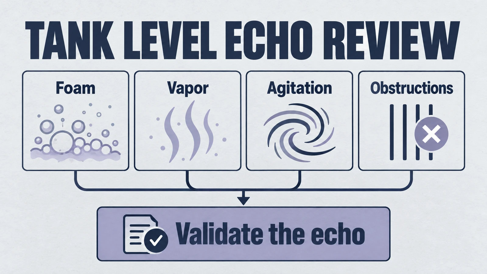
False echo is one of the most expensive hidden failure modes in ultrasonic tank level sensing. Systems look stable during bench commissioning, but once foam grows, vapor concentration shifts, or agitation starts, the level output jumps, freezes, or tracks the wrong reflector. The plant still receives a signal, yet the signal no longer represents process truth.
For many teams, this is where troubleshooting drifts into random trial-and-error. Someone raises gain, someone else adds averaging, another team changes mounting angle, and a week later the issue returns under a different operating condition. The real problem is that false echo is not a single bug. It is a multi-factor interaction between acoustic physics, installation geometry, and filtering strategy.
This playbook is written for engineering and procurement teams that need repeatable outcomes, not one-off fixes. It translates common failure symptoms into practical countermeasures, maps them to available models, and ends with an RFQ checklist that reduces rework before quotation. For product baseline context, start with the ultrasonic sensor families overview and the ultrasonic transducer supplier capability page.
Problem Context
Product path for this search intent
Match the article topic to the right YJ Piezo product page
Use this article when sensor performance depends on target distance, beam angle, housing material, liquid behavior, or false echo control. For "False Echo in Tank Level Sensing: Foam, Vapor, and Agitation Countermeasures", the practical value is in turning the topic into a measurable selection or sourcing decision.
- Ultrasonic Sensors
Distance, level, and detection sensor portfolio
- Flow Measurement Transducers
Bubble and flow-related ultrasonic sensing paths
- Air Acoustic Transducers
Air-coupled transducers for range and presence detection
In level applications, false echo usually appears as one of four operational symptoms:
- Stable but wrong level: The sensor locks to a fixed internal object such as a ladder rung, agitator blade, nozzle edge, or welded seam.
- Intermittent spikes: Readings jump during filling, CIP, or mixing cycles when foam and surface turbulence rise rapidly.
- Signal dropouts: Echo confidence collapses in dense vapor or heavy foam, then recovers when process conditions calm down.
- Slow drift: Output shifts with temperature and headspace composition, especially in tall tanks and outdoor installations.
These symptoms are often misclassified as electronics instability. In reality, most cases are acoustic interpretation errors. The sensor receives valid reflections, but the strongest or earliest return is not always the true liquid surface.
Why "Detectable" Is Not the Same as "Reliable"
A commissioning test with clean water in a quiet tank proves only one condition. Industrial reality adds changing media, thermal gradients, vapor density shifts, deposits, and mechanical vibration. Under these conditions, a setup that "detects level" can still fail control requirements for repeatability and traceability.
For deeper physics background on multiphase acoustic behavior, refer to acoustic void engineering in multiphase media. For blind-zone interactions that can amplify false returns at short distance, see blind zone limitations in ultrasonic sensing.
Business Impact of Untreated False Echo
When false echo persists, impact extends beyond measurement quality:
- Overfill risk and safety exposure in chemical storage.
- Pump dry-run, cavitation, and maintenance events caused by false low-level outputs.
- Inventory mismatch between historian data and actual tank volume.
- Unplanned engineering cycles due to repeated parameter tuning.
- Procurement delays when the first quoted model cannot pass site acceptance.
The correct objective is not "remove all noise." The objective is to design a measurement architecture where the true surface echo remains dominant and interpretable across expected process states.
Where Projects Usually Lose Time
Most delay does not come from one major design mistake. It comes from three repeated process gaps: first, no one defines which physical interface must be tracked when foam appears; second, troubleshooting changes multiple variables at once so results cannot be attributed; third, acceptance criteria are written after pilot installation, not before. These gaps create a cycle where each team sees partial evidence and assumes a different root cause.
A robust project flow therefore needs role clarity. Process engineers own interface definition and operating windows. Instrument engineers own geometry and signal strategy. Procurement owns requirement completeness and model assumptions in the RFQ package. If these responsibilities are merged too late, the same false echo symptom will reappear at FAT, SAT, and expansion phases with different labels.
For procurement-facing teams, this distinction matters because quote comparison becomes meaningless when each supplier is implicitly solving a different problem statement. The goal of this playbook is to force a shared technical baseline before commercial negotiation starts.
Engineering Constraints
False echo control depends on constraint clarity. Before selecting a model or tuning filters, lock the following engineering boundaries.
1) Foam Behavior Is a Dynamic Acoustic Boundary
Foam is not a static surface. Bubble size distribution, wetness, and collapse rate change with process phase. Light wet foam may produce a weak but trackable surface echo. Dry, thick, or layered foam can absorb or scatter acoustic energy and either hide the liquid surface or create a false stable boundary.
Therefore, RFQ and tuning must define which interface matters: top of foam, liquid below foam, or a fallback appropriate-state when neither is robustly visible. Without this definition, teams may optimize for the wrong output behavior.
2) Vapor Composition Alters Propagation and Echo Confidence
Headspace vapor does two things at the same time: it shifts effective sound velocity and increases attenuation. Even with temperature compensation, heavy solvent or acid vapor can lower echo amplitude enough that internal structures become comparatively stronger reflectors.
This is why vapor-heavy tanks need explicit compensation and validation planning. Use temperature compensation and calibration guidance together with field drift troubleshooting methods to define acceptable error windows.
3) Agitation and Internal Structures Create Competing Echo Paths
Agitators, baffles, coils, ladders, and narrow nozzles generate strong reflections. During high turbulence, the true liquid surface echo may become intermittent while static structures remain stable. If teach-in masking is not configured carefully, the sensor may lock to the wrong target or oscillate between returns.
Any robust design must include geometric clearance analysis, mounting axis control, and an obstacle map in the same document as electrical settings.
4) Beam Geometry and Installation Govern Echo Ranking
False echo is often an installation problem before it is an algorithm problem. Nozzle depth, tilt, and stand-off distance decide whether side-wall reflections enter the main lobe. A narrow beam helps, but narrow beam alone does not compensate for poor mechanical placement.
Where turbulence is unavoidable, stilling well or guided mechanical isolation can produce cleaner returns than software filtering alone.
5) Filter Strategy Must Match Control Objective
Filtering is a trade-off between stability and responsiveness. Over-aggressive filtering suppresses spikes but delays true level change. Under-filtering responds fast but amplifies transient false echoes. The right setting depends on process dynamics and control loop tolerance, not a generic default profile.
6) Housing and Material Compatibility Set Long-Term Stability
If process chemistry degrades sensor face or connector sealing, false echo may evolve from intermittent to chronic. Material selection is therefore part of false echo prevention. For harsh process environments, compare steel and polymer options using stainless steel housing sensor options and compatible process-grade models such as UltraNova2.
7) Commissioning Data Quality Determines Tuning Quality
Teams often tune with incomplete data: no timestamped process tags, no agitation state marker, no temperature trace, and no record of manual level references. In that setup, every trend can be interpreted in multiple ways, so tuning converges slowly or not at all. If you cannot correlate output anomalies with process windows, tuning is guesswork.
At minimum, log level output, raw echo confidence (if available), product temperature, headspace temperature, agitator status, and major process transitions such as fill, discharge, and CIP. This does not require a complex data platform. Even a temporary synchronized log sheet for one production shift can expose which disturbance dominates false echo behavior.
Before approving final settings, run the same test script on at least two non-consecutive days. One-day success in level sensing can hide repeatability failure under different ambient and operating conditions.
Selection Matrix
Use this matrix before parameter tuning. It links observed symptoms to dominant causes and preferred countermeasures.
| Field Symptom | Likely Dominant Cause | Primary Countermeasure | Verification Check |
|---|---|---|---|
| Stable wrong level near fixed distance | Lock on ladder, nozzle lip, or agitator reflector | Re-align mounting axis, apply echo mask for static structures | Empty-tank map plus controlled fill profile |
| Spikes during mixing cycles | Surface turbulence and multipath competition | Adaptive averaging and response-time tuning | Trend variance before/after mixing windows |
| Frequent echo loss in hot vapor phase | Attenuation and velocity mismatch in headspace | Compensation tuning + process-specific reference validation | Thermal ramp test with known level markers |
| Measurement tracks foam cap, not liquid | Foam surface dominates return path | Define target interface intent; use stilling well if needed | Compare manual dip vs sensor trend by process phase |
| Random jumps near full tank | Near-nozzle reflections and reduced clearance | Adjust stand-off and nozzle geometry constraints | Top-end level sweep with fixed step increments |
Field Troubleshooting Workflow (Step-by-Step)
Use the following sequence to avoid random parameter changes.
- Freeze the baseline: Record current setup, output mode, filter parameters, and process state. Do not tune anything yet.
- Separate static vs dynamic error: Test with mixer off, then mixer on. If error appears only under agitation, prioritize turbulence countermeasures.
- Run empty or low-level echo mapping: Identify fixed reflectors from nozzle, walls, ladders, and internals.
- Validate installation geometry: Check axis, tilt, stand-off, and beam clearance against tank internals.
- Apply one countermeasure at a time: Example order: alignment correction -> echo masking -> filter optimization -> stilling well.
- Quantify response trade-off: After each change, compare noise reduction against response delay.
- Re-test across process windows: Include startup, steady operation, cleaning, and temperature swing.
- Lock acceptance criteria: Define pass/fail thresholds before moving from sample to pilot scale.
Teams that skip Step 1 and Step 8 usually repeat the same troubleshooting cycle every time process conditions change.
Countermeasure Priority by Failure Severity
Not every false echo event deserves the same response speed. Use severity to prioritize mitigation resources and avoid overengineering low-impact cases.
| Failure Pattern | Operational Severity | Recommended Action Window | Preferred Mitigation Layer |
|---|---|---|---|
| False high-level near overfill threshold | Critical safety and production impact | Immediate containment + rapid engineering review | Geometry + masking + acceptance retest |
| False low-level triggering premature refill/pump logic | High process disruption risk | Same shift correction plan | Filter-response rebalance + interface validation |
| Intermittent spikes without control upset | Moderate data-quality impact | Scheduled optimization cycle | Adaptive averaging and process-window tuning |
| Minor offset under rare process state | Low operational impact | Document and monitor trend | Acceptance-band update + periodic verification |
Model Mapping
Model choice should be framed by false-echo risk profile, not only range headline. For full series context, review sensor product families.
| Application Need | Primary Model | Backup Model | Why This Mapping Works |
|---|---|---|---|
| Longer-range tank level with internal structures | SR80 | SR55 | Stronger industrial level focus with filtering and interface flexibility |
| Moderate-range process tanks with turbulence windows | SR55 | UltraNova2 | Good balance of control integration and process robustness |
| Harsh washdown or aggressive vapor exposure | Stainless Housing | UltraNova2 | Material durability helps preserve long-term echo stability |
If false echo remains unresolved after geometry correction and compensation tuning, do not force endless parameter iteration. Run a technology-level comparison with ultrasonic vs pressure level sensing trade-offs to confirm architecture fit.
Interface Notes for Control Teams
In noisy plants and long cable runs, define output architecture early. A stable acoustic design can still fail at integration if interface constraints are postponed to late commissioning. Include expected output type, fault-default behavior, and signal conditioning assumptions in the same decision package as mechanical design.
Practical Model Pairing Logic for Pilot Programs
For tank projects with uncertain foam and vapor behavior, avoid single-model procurement from day one. Start with a primary + backup model pair and evaluate both during pilot acceptance. A two-model strategy usually costs less than repeated redesign, especially where shutdown windows are expensive.
A common mapping is SR80 as the primary candidate for longer range and complex internal reflections, with SR55 as the backup for medium-range robustness and integration flexibility. In chemically aggressive or washdown-heavy environments, include stainless housing options in the same comparison to avoid material-induced drift later in lifecycle.
Document why each model was shortlisted, which risks each model is expected to mitigate, and what test result would trigger model switch. Without this trigger definition, pilot data may be interpreted to support pre-selected preferences rather than engineering evidence.
RFQ Checklist
For false-echo-sensitive tank projects, RFQ quality determines quotation quality. Use this checklist to reduce model mismatch and pilot-stage rework.
- Range envelope: Minimum, normal, and maximum distance including top-end and near-nozzle constraints.
- Process environment: Temperature profile, humidity, vapor type, expected foam behavior, and cleaning cycle details.
- Internal tank map: Ladder, agitator, baffle, coil, nozzle depth, and any temporary obstructions.
- Output interface: Required signal type and integration constraints in the target control system.
- Power constraints: Supply range, grounding policy, and cable requirements.
- Validation method: Required acceptance test flow, pass/fail thresholds, and reporting format.
- Commercial scope: Sample quantity, pilot quantity, annual forecast, and lead-time expectation.
- Sourcing policy: Need for backup model and supplier qualification evidence.
Mandatory five fields for RFQ handoff: range + environment + output interface + power + quantity + lead-time. If these are missing, quote comparison will be unreliable.
Copy-Paste RFQ Starter
Application: [tank level / process]
Range: [min / normal / max]
Environment: [foam, vapor, agitation, temperature]
Output + Power: [interface], [supply range]
Quantity + Lead Time: [sample/pilot/annual], [required date]
Preferred Model Pair: [primary], [backup]
Minimum Site Acceptance Flow for False-Echo Control
Before mass rollout, require a short but disciplined acceptance flow. This prevents project teams from declaring success based on one stable screenshot.
- Baseline reference: Verify empty and near-full endpoints with manual reference.
- Static condition run: Mixer off, no fill/discharge, establish noise floor.
- Dynamic agitation run: Mixer on at expected operational profile.
- Foam/vapor stress window: Test under worst expected process condition, not nominal only.
- Thermal variation check: Validate during process temperature transition if applicable.
- Control integration check: Confirm output scaling, fault-default behavior, and alarm logic.
- Repeatability run: Repeat key windows on another day or batch.
- Sign-off package: Archive settings, trend logs, and pass/fail evidence for future expansion.
If your organization follows supplier qualification gates, align this SAT flow with your internal sourcing process through the supplier qualification pathway so engineering and procurement approve the same evidence set.
You can route procurement and engineering qualification through supplier capability overview and submit requirements from the contact page.
FAQ
What is the difference between false echo and signal loss?
Signal loss means no reliable return is detected. False echo means a strong return is detected from the wrong target. They require different countermeasures, so diagnose them separately.
Can filtering alone solve false echo in agitated tanks?
Usually not. Filtering can reduce visible noise but cannot fully correct a poor acoustic path. Start with geometry and echo-source control, then tune filters.
When should we use a stilling well?
Use it when turbulence and foam repeatedly overpower direct free-space measurement and process constraints allow mechanical isolation. Validate clogging and maintenance risks before deployment.
How do we decide between SR80 and SR55 for false-echo-prone tanks?
Use operating range, tank geometry, and false-echo profile as primary criteria. Treat model selection as a paired comparison with a backup candidate, not a single-name quote.
How should acceptance testing be structured?
Include static reference checks, agitation windows, thermal variation windows, and top-end/low-end boundary checks. Define pass/fail values before sample installation.
When is it better to evaluate another sensing architecture?
When process conditions continuously violate ultrasonic assumptions even after geometry and compensation optimization. Run a structured architecture comparison instead of prolonged parameter tuning.
How can procurement avoid repeated redesign cycles?
Use a requirement-complete RFQ and demand primary/backup model mapping with explicit assumptions. This moves risk visibility forward before commercial lock.
Request Engineering Support
If your project involves foam, vapor, and agitation at the same time, send your tank geometry and process windows with the RFQ checklist. We can propose a model pair, tuning path, and validation scope designed for stable commissioning.
- Email Engineering for RFQ
- Submit Requirements via Contact Page
- Review SR80 Product Details
- Review SR55 Product Details
Related Technical Reading
Engineering decision notes
Ultrasonic sensing and detection
Use this article when sensor performance depends on target distance, beam angle, housing material, liquid behavior, or false echo control. For "False Echo in Tank Level Sensing: Foam, Vapor, and Agitation Countermeasures", the practical value is in turning the topic into a measurable selection or sourcing decision.
YJ Piezo treats ultrasonic sensing as an acoustic interface problem: transducer frequency, beam shape, housing, drive electronics, and target environment are reviewed together.
Selection checks
- Define target range, dead zone, beam angle, and mounting geometry before choosing the sensor family.
- Check the medium, target surface, temperature swing, foam, vapor, and side-wall risk.
- Separate detection repeatability from ideal lab accuracy when the sensor will operate in a tank, tube, or moving line.
Failure risks
- A sensor can pass bench distance tests and still fail in tanks with foam, agitation, vapor, or narrow geometry.
- Changing only frequency without reviewing beam angle and mounting can increase false echoes.
- Ignoring housing material or sealing requirements can shorten lifetime in washdown or chemical environments.
RFQ details
- What is the minimum and maximum detection distance?
- Is the target liquid, solid, sheet material, air flow, or a moving object?
- What temperature, humidity, IP rating, and output signal does the system require?
Relevant YJ Piezo pages
- Ultrasonic Sensors
Distance, level, and detection sensor portfolio
- Flow Measurement Transducers
Bubble and flow-related ultrasonic sensing paths
- Air Acoustic Transducers
Air-coupled transducers for range and presence detection
Application FAQ
- What makes an ultrasonic sensor page useful for procurement?
- It should connect range, beam angle, output signal, housing, mounting, and environmental limits to a concrete use case. A model name alone is not enough for reliable supplier comparison.
- Which information speeds up an ultrasonic sensor RFQ?
- Send the target material, distance range, installation geometry, output interface, temperature range, IP rating, and whether the application involves foam, vapor, liquid, or moving objects.