
Key Design Parameters of Spherically Curved Piezo Elements: Radius, Aperture, and Thickness
Focused ultrasonic transducers often start with a deceptively simple sentence: "Use a spherically curved piezo to focus the beam." Then reality shows up. The beam does not focus exactly where CAD predicted. The resonance shifts when the element is bonded. Two parts from the same batch behave slightly differently. The "perfect" curvature is difficult or expensive to manufacture, and a small change in one geometric parameter quietly wrecks another.
This article is written for designers who already know the basics of piezo materials and thickness-mode resonance, and who want a practical mental model for spherically curved (custom spherical-cap piezo) ceramics. It is not a recipe. It is a map of the trade space.
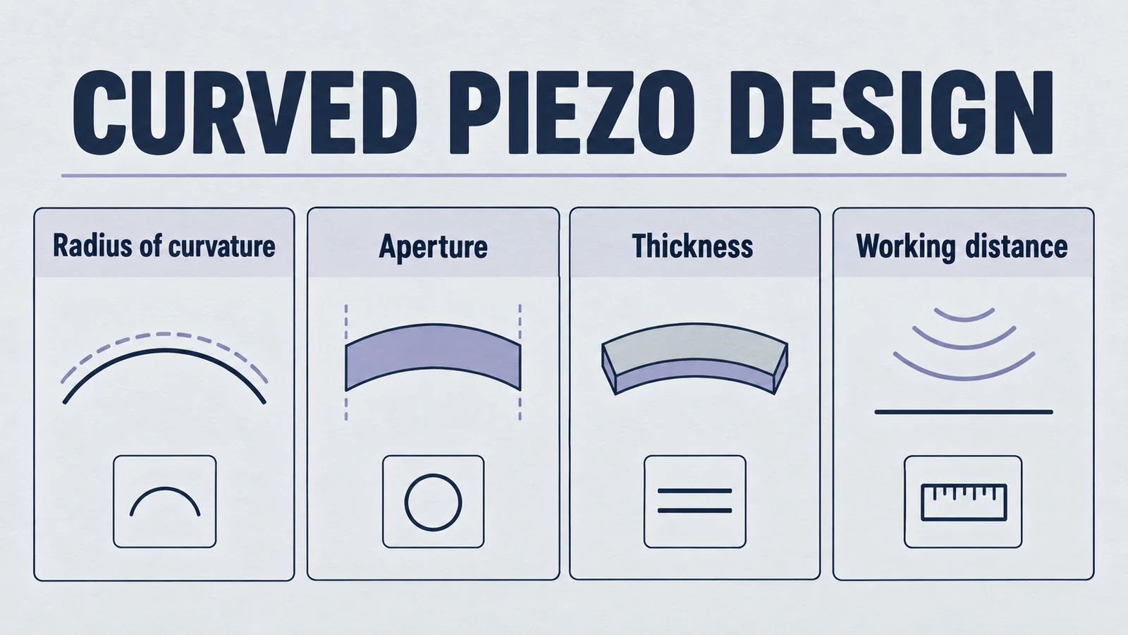
We will focus on three parameters you specify early in a design.
- Radius of curvature (R). Sets the geometric tendency to converge.
- Aperture diameter (D). Sets the "lens size" and controls focal spot and intensity.
- Ceramic thickness (t). Dominantly sets thickness-mode resonance, but also couples into curvature stress, mode purity, and manufacturability.
Product path for this search intent
Match the article topic to the right YJ Piezo product page
Use this article when curved ceramic geometry, focal distance, acoustic intensity, and assembly tolerances matter more than a flat element comparison. For "Key Design Parameters of Spherically Curved Piezo Elements: Radius, Aperture, and Thick...", the practical value is in turning the topic into a measurable selection or sourcing decision.
- Spherical Cap Piezoelectric Ceramics
Focused ceramic shapes for OEM ultrasonic assemblies
- Piezoelectric Ceramics
Shape and material options for custom design
- Air Acoustic Transducers
Acoustic interface references for beam behavior
The key message: these parameters do not act independently. Their interactions are why focused piezo design is inherently compromise-driven.
1) What a "spherical-cap piezo" really is
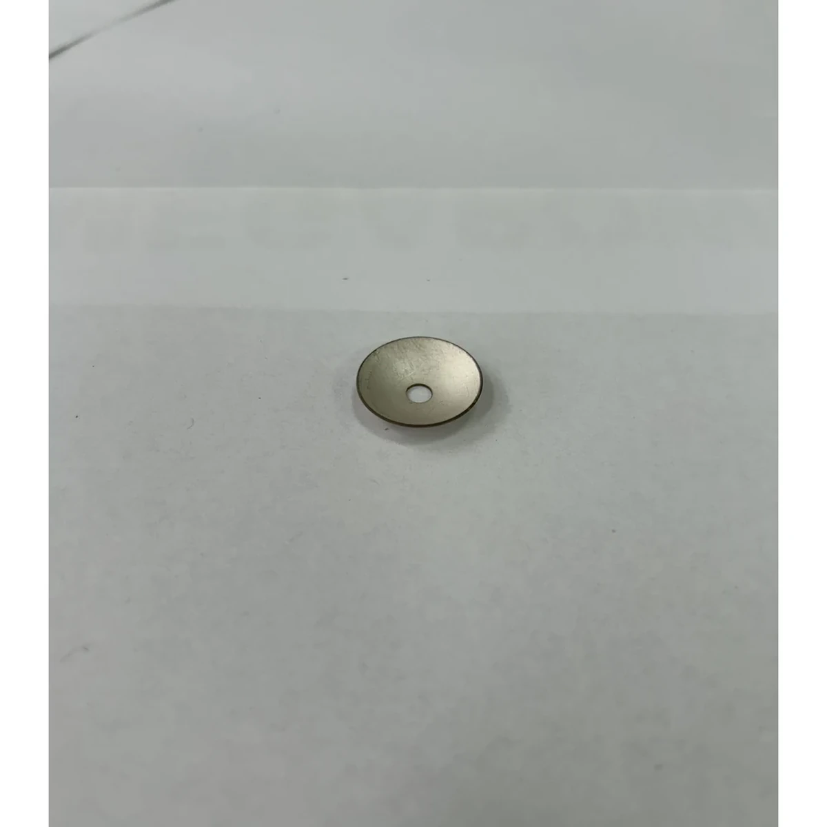
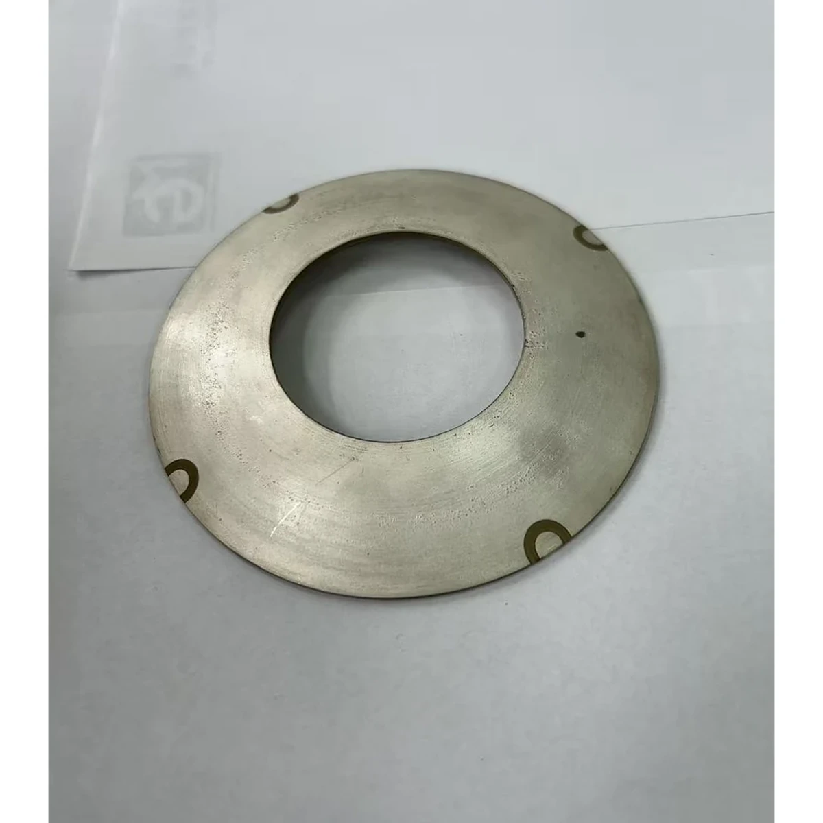
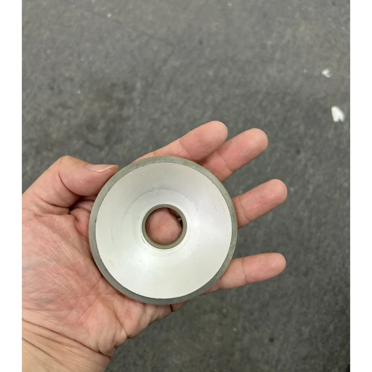
A spherical-cap piezo element is a piezoelectric ceramic shell segment with a concave/convex spherical surface. In practice it is part of a stack.
- The ceramic is typically electroded on its inner and outer surfaces.
- It is usually bonded to a backing, carrier, or metal cup, and coupled to a front medium (water, gel, tissue, air with matching layers, etc.).
- The assembly creates an acoustic boundary condition that is never the same as the free ceramic.
The element is therefore not just a "geometric lens." It is a resonant electromechanical structure, under stress, with boundary conditions.
2) Radius of curvature. Focal distance is not a single number
2.1 First-order geometry
If you grew up on optics analogies, you will see radius R and think "focal length." In a purely geometric sense, a spherical cap tends to focus around a distance comparable to its radius. That intuition is useful, but incomplete.
2.2 Why the actual focus shifts
In ultrasonics, the "focus" you care about is a consequence of phase distribution across the aperture. Radius drives a phase curvature. But phase at the radiating surface is altered by things that have nothing to do with the machined curvature.
Common focus-shifters:
- Loading by the front medium. Water or tissue loads the radiating surface and changes effective vibration distribution. The speed of sound and attenuation in the medium also shift the location of maximum pressure.
- Bond layer thickness and stiffness. A few tens of microns of adhesive variation can change boundary stiffness enough to alter mode shape, especially for thin or highly curved caps.
- Backing impedance. A high-impedance backing can reflect energy back into the ceramic and alter effective phase. A lossy backing can broaden bandwidth but reduce peak pressure.
- Manufacturing curvature deviation. "R" is a nominal value. Real parts have radius tolerance, surface waviness, and local deviations.
So, focus is best treated as a distribution. Your test data will likely show a focal region (depth of focus) rather than a perfect point.
2.3 Trade-off. Shorter R increases convergence but increases sensitivity
Designers often push for smaller radius to get a tight focus. The cost is not just "harder manufacturing." It is also higher sensitivity to small errors.
- Smaller R increases wavefront curvature. Any local deviation, tilt, or bonding non-uniformity contributes more phase error.
- Smaller R often means higher mechanical stress during forming/sintering and higher risk of microcracks or warpage.
- In assemblies, smaller R can increase the chance that non-thickness modes participate, shifting resonance and adding sidelobes.
A good rule of thumb in design reviews: if you ask for aggressive curvature, you must budget more for tolerance control and more for test iteration.
3) Aperture diameter. The hidden driver of intensity and spot size
3.1 Aperture and energy density
Aperture diameter D is the size of the active radiating surface. Increase D and you are giving the system more area to radiate acoustic power. If electrical drive and coupling are stable, a larger aperture can deliver higher on-axis pressure at focus.
But "more area" is not a free lunch.
- The larger the aperture, the more difficult it is to maintain uniform electromechanical drive across the surface.
- Larger caps are more prone to non-uniform thickness, electrode non-uniformity, and bonding gradients.
3.2 Aperture and focal spot size
Focal spot size is primarily governed by how much of the wavefront you collect and how strongly you converge it. In simplified terms:
- Bigger D tends to reduce spot size and increase energy concentration.
- Bigger D also tends to reduce depth of focus (a tighter waist means a shorter working range).
In other words, D pushes you toward a sharper focus, but often at the cost of less forgiving alignment and less usable axial range.
3.3 Trade-off. Bigger D increases alignment and assembly risk
A focused transducer is an alignment machine disguised as a ceramic.
- A larger aperture can make target-axis alignment more demanding. Pure rigid tilt rotates the field; clipping, interfaces or nonuniform deformation may create actual aberration.
- A small eccentricity in mounting becomes a measurable focal shift.
- A larger active area increases the chance that support fixtures or metal cups introduce asymmetric constraints.
If your product is intended for a manufacturing environment with inevitable tolerance stack-up, a slightly smaller aperture can be the difference between stable production yield and constant rework.
4) Thickness. Frequency-determining. But also a coupling knob
4.1 Thickness-mode resonance is the starting point
For most piezo ceramics used as thickness-mode radiators, the fundamental resonance frequency
is primarily set by thickness t and the effective acoustic velocity of the ceramic.That statement is true enough to be useful, but it invites a dangerous assumption: "set t, get f." In practice, you set t, then the system moves f.
4.2 Why frequency shifts from the nominal thickness value
Real-world frequency depends on the entire mechanical and acoustic system.
- Curvature changes stiffness distribution. A curved shell is not the same as a flat plate. Curvature can introduce membrane-like behavior and alter modal coupling.
- Electrode mass and plating. Thick or uneven electrodes add mass and can slightly shift resonance, particularly for higher frequencies.
- Bonding layers. Adhesive adds both mass and compliance. Variation changes effective boundary conditions.
- Preload and clamping. If the cap is mechanically constrained, resonance can move and additional modes can appear.
So thickness is best treated as the dominant frequency lever, not the only lever.
4.3 Trade-off. Thinner for higher frequency increases fragility and process sensitivity
High-frequency focused elements often push toward thin ceramics. That creates constraints.
- Thin ceramics are easier to crack during handling, bonding, or thermal cycling.
- Thin caps are more sensitive to thickness tolerance. A small absolute deviation is a larger percentage error.
- Thin shells can increase coupling to radial or flexural modes, contaminating the thickness response and complicating impedance matching.
If you need a high frequency, you also need a plan for yield, handling, and repeatable assembly.
5) Interdependence. Geometry, resonance behavior, and manufacturability are coupled
Here is where design gets non-intuitive.
5.1 R, D, t form a coupled triangle
You can think of the focused element as constrained by three coupled "budgets":
- Acoustic focusing budget. Controlled by R and D. You want phase curvature and sufficient aperture.
- Resonance and mode purity budget. Controlled by t, but strongly influenced by curvature and boundary constraints.
- Manufacturing and yield budget. Controlled by how aggressive the curvature is, how large the part is, and how thin it is.
Push any corner too far and another corner pushes back.
- Smaller R and larger D improve convergence but increase sensitivity to curvature error and assembly tilt.
- Smaller t increases frequency but increases fragility, thickness tolerance sensitivity, and risk of mode contamination.
- Larger D increases power capability but increases electrode uniformity challenges and bonding non-uniformity.
5.2 "Optimizing" a single parameter often degrades the system
A few classic failure patterns:
- Radius-only optimization. You set R to hit a focal distance. The part focuses "near enough" in air, but in water the focal peak shifts, sidelobes rise, and the system becomes sensitive to small tilt. You end up adding mechanical alignment hardware, which increases cost and volume.
- Aperture-only optimization. You increase D for tighter spot and higher intensity. The assembly then shows batch-to-batch variation because bonding gradients across a larger surface introduce phase errors. The field becomes less repeatable than the smaller aperture design.
- Thickness-only optimization. You set t for the target frequency. After bonding, resonance shifts and impedance changes. You then add matching layers or change backing. Now the focal behavior changes again because mode distribution changed.
The lesson is not "don't optimize." The lesson is optimize the system with a tolerance model, not a single nominal geometry.
6) Uncertainty and tolerances. The design is only as good as the deviation budget
In focused ultrasonics, small geometric deviations can become large acoustic errors because the device is essentially a phase-sensitive radiator.
6.1 What deviations matter most
Not all tolerances hurt equally.
- Curvature deviation (ΔR and local waviness) causes phase error across the aperture.
- Thickness non-uniformity (Δt across the cap) shifts local resonance and creates non-uniform vibration amplitude.
- Aperture edge quality affects boundary conditions. Chips or edge defects can seed cracks and introduce asymmetry.
- Electrode uniformity affects drive distribution and can shift resonance slightly.
6.2 Practical reality. You design with distributions, not single values
A robust focused design usually needs:
- A specified tolerance envelope for R, D, and t, including measurement method (how is R verified? how is thickness measured on a curved surface?).
- An assembly plan that controls bond-line thickness and concentricity.
- A test plan that measures not only impedance but also acoustic field (pressure map or hydrophone scan) across multiple units.
If your design process assumes ideal geometry and perfect bonding, the first production build will be a very expensive education.
7) A practical way to think. Start with what must be true
Because this is multi-variable, it helps to start with constraints instead of chasing an "optimal" geometry.
7.1 Define what is non-negotiable
Common non-negotiables:
- Required frequency range or bandwidth.
- Allowed drive voltage and duty cycle (thermal limits are real).
- Required focal distance range in the actual medium.
- Maximum allowable transducer size.
- Production yield targets.
Once these are set, R, D, and t become decision variables inside a constraint box.
7.2 Expect iteration and allocate it deliberately
Even with good modeling, you will iterate because:
- Material properties vary with batch, temperature, and poling condition.
- Boundary conditions are hard to model accurately.
- The acoustic field in a real medium involves attenuation, scattering, and sometimes cavitation effects.
If you cannot afford iteration, you must choose a more conservative geometry. Otherwise you are betting the project on ideal assumptions.
8) Engineering takeaways
- Radius (R) sets the geometric tendency to converge, but the actual focus depends on loading, bonding, and phase error. Smaller R increases sensitivity.
- Aperture (D) strongly drives focal spot size and energy density, but increases alignment and manufacturability risk. Bigger D can reduce robustness.
- Thickness (t) is the dominant frequency lever, but resonance shifts with curvature and assembly boundary conditions. Thinner parts raise fragility and mode-coupling risk.
- Interdependence is the whole story. Optimizing one parameter often degrades another because field formation, resonance behavior, and manufacturing yield are coupled.
- Design with tolerances and distributions. A focused piezo is a phase device. It punishes optimistic assumptions.
If you want to make focused ultrasonic products that ship reliably, the "winning" design is rarely the one with the smallest spot in a simulation. It is the one that still behaves acceptably when curvature is off by a little, bond lines vary by a little, and the medium is messier than the lab.
If you are documenting a focused element for an OEM program, consider including: nominal R/D/t, tolerance ranges, measurement methods, impedance curves before and after bonding, and a representative acoustic field scan in the target medium. Those artifacts do more for engineering trust than any datasheet headline.
Need engineering support optimizing your transducer design? Our team can review your application requirements and recommend R, D, and t combinations that balance performance with manufacturing reality.
Engineering decision notes
Focused and curved piezo ceramics
Use this article when curved ceramic geometry, focal distance, acoustic intensity, and assembly tolerances matter more than a flat element comparison. For "Key Design Parameters of Spherically Curved Piezo Elements: Radius, Aperture, and Thick...", the practical value is in turning the topic into a measurable selection or sourcing decision.
YJ Piezo reviews curved ceramics as geometry-sensitive acoustic components, where aperture, curvature, thickness, electrode layout, and mounting boundary all affect the usable focus.
Selection checks
- Define focal distance, aperture, medium, and allowable package depth before selecting curvature.
- Review resonance behavior with the intended mounting boundary, not only as a loose ceramic.
- Plan sample validation around beam behavior, impedance spread, and thermal drift.
Failure risks
- A curved part can meet dimensional drawings but miss the intended acoustic focus if the boundary condition changes.
- Mode coupling can create unstable frequency behavior after assembly or thermal loading.
- Over-optimizing peak intensity can reduce practical tolerance to alignment and field conditions.
RFQ details
- What focal distance, aperture, and working medium are required?
- Is the ceramic bonded, clamped, housed, or used as a bare focused element?
- Do you need impedance spread, acoustic validation, or geometry tolerance records?
Relevant YJ Piezo pages
- Spherical Cap Piezoelectric Ceramics
Focused ceramic shapes for OEM ultrasonic assemblies
- Piezoelectric Ceramics
Shape and material options for custom design
- Air Acoustic Transducers
Acoustic interface references for beam behavior
Application FAQ
- Why are curved piezo ceramics harder to specify than flat ceramics?
- Curvature changes the acoustic field and can interact with mounting, bonding, and drive conditions. The useful specification must include geometry, focus, medium, resonance behavior, and assembly boundary.
- What should be validated before buying focused piezo ceramics in volume?
- Validate focal distance, impedance spread, frequency stability after assembly, thermal behavior, and the tolerance stack between ceramic geometry and the final housing.