
When Not to Use Focused Piezoelectric Ceramics
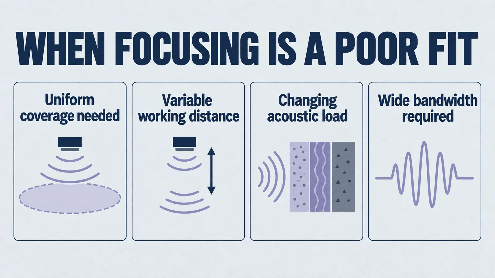
Focused piezoelectric ceramics are seductive.
On paper they offer a clean promise. Higher intensity at a focal spot, better signal-to-noise, and a smaller effective beam.
In practice they also behave like an engineered trap for the wrong system. A focused element is not “a stronger transducer”. It is a transducer that converts tolerance, loading variation, and alignment error into performance drift.
This article is intentionally failure oriented. The goal is to help you reject focused ceramics early when the physics and manufacturing reality say they will cost you schedule, yield, and reliability.
Product path for this search intent
Match the article topic to the right YJ Piezo product page
Use this article when curved ceramic geometry, focal distance, acoustic intensity, and assembly tolerances matter more than a flat element comparison. For "When Not to Use Focused Piezoelectric Ceramics", the practical value is in turning the topic into a measurable selection or sourcing decision.
- Spherical Cap Piezoelectric Ceramics
Focused ceramic shapes for OEM ultrasonic assemblies
- Piezoelectric Ceramics
Shape and material options for custom design
- Air Acoustic Transducers
Acoustic interface references for beam behavior
If you came here hoping for a list of clever tricks to make focusing behave in a messy OEM product, you are in the wrong place. This is a decision filter. It is designed to stop bad projects before they consume your test budget.
What “focused” really means in system terms
A focused ceramic is a custom spherical-cap piezo ceramic, or a flat element coupled to an acoustic lens, that produces a converging wavefront. The wavefront curvature is designed so phases add coherently at a target distance, forming a peak pressure region.
That definition sounds optical. The consequences are not.
The important shift is this.
A uniform field design is robust to variation. A focused field design is optimized for one geometry, one load, one standoff, one alignment.
Once you accept that, the “when not to use it” list becomes obvious.
Focus is a constraint amplifier
A focused transducer does not merely create a focal spot. It also creates an unusually strong coupling between small physical errors and measurable output.
- A small mechanical shift becomes a large pressure change.
- A small loading change becomes a focal shift.
- A small potting or adhesive variation becomes an acoustic lens you never designed.
If your organization lives in the real world. Tolerances, operators, temperature swings, and materials. Focus will happily convert that reality into scatter in your test results.
Decision filter. Start with the field requirement
Before you think about focal length, ask a blunt question.
Do I actually need a spatial pressure peak, or do I need a uniform field over an area or volume.
If you need a uniform or quasi-uniform field, a focused element is usually the wrong tool.
Use-cases that demand uniformity
If your requirement is any of the following, you are typically in uniform-field territory.
- You need consistent excitation across a surface, not a single hot spot.
- You want repeatable coupling across parts with geometric variance.
- Your process needs “average energy delivery” rather than “peak energy delivery”.
- You have to meet safety or material constraints tied to local intensity.
- You want predictable performance across users and environments.
A focused beam fights these requirements. It creates gradients on purpose.
That is not a minor mismatch. It is a specification-level contradiction.
A quick mental test
If your success metric is written like this.
- “At least X everywhere in this region.”
Then you are not asking for focus. You are asking for coverage.
If your success metric is written like this.
- “As high as possible at one location.”
Then focus might be relevant. But only if you can control that location.
Failure mode 1. Local intensity becomes the problem
A focused field raises peak pressure. That is the point.
But many OEM systems fail not because they cannot generate enough pressure. They fail because where the pressure goes becomes uncontrollable or unsafe.
When peak intensity is a liability
Avoid focused ceramics when any of these risks are dominant.
- Material damage or micro-cracking. Brittle substrates, thin films, sintered parts, and bonded interfaces can be damaged by localized stress.
- Unwanted cavitation. In liquids, the focal region can cross cavitation thresholds. Cavitation is not a mild side effect. It is a regime change that introduces erosion, noise, and variability.
- Thermal hotspots. If absorption is non-uniform, focusing concentrates heating and can trigger runaway temperature rise locally.
- Process non-uniformity. Cleaning, mixing, degassing, or agitation processes often degrade when you create a single energetic region and starve the rest.
- Regulatory or safety thresholds tied to intensity. If your product is judged by peak exposure, focusing makes the worst-case tighter and harder to defend.
If your QA plan treats “maximum local intensity” as a controlled parameter, a focused design makes that control harder, not easier.
The ugly reality. You do not ship averages
Engineering teams often validate a focused design by showing a beautiful peak on a lab rig. Manufacturing then ships a distribution.
Your customers do not experience your best sample. They experience the tails.
In focused systems, the tails are where hotspots, cavitation, and failures live.
Failure mode 2. Alignment turns into an electrical performance spec
A focused ceramic converts mechanical alignment into acoustic performance. That sounds trivial until you quantify it.
If your effective focal spot is small, then a small offset is a big miss.
Common alignment realities in OEM systems
Most production assemblies include some combination of these.
- Part-to-part tolerance stack-up.
- Adhesive thickness variation.
- Fixture wear.
- Housing deformation under clamping.
- Thermal expansion mismatch.
- User-driven placement error.
- Creep and relaxation over time.
Ordinary linear acoustic fields vary continuously with position. Steep focal gradients can make small alignment changes important, while threshold detection, cavitation or controller switching may create abrupt system outcomes. Focusing alone does not imply discrete degradation or guarantee a uniform unfocused field.
A 1 mm shift in standoff may be negligible in a broad beam. The same 1 mm can move you off peak in a tight focus and cut your effective amplitude dramatically.
If your mechanical team cannot hold alignment and standoff tightly and repeatedly, you should assume your acoustic output will become a distribution, not a number.
That is how yield loss starts.
A production framing that usually hurts
If the acoustic requirement is written in electrical language, for example “must hit Vpp at the receiver” or “must reach X dB SNR,” you may be hiding the real constraint.
In a focused design, you are implicitly specifying mechanical tolerances. If those tolerances are not in the drawing, they will show up as field failures.
Failure mode 3. Loading changes the focus. Then your calibration dies
Focus is not only geometry. It is geometry in a medium.
The load defines sound speed, attenuation, impedance, and boundary conditions. Change the load and the designed wavefront curvature is no longer “right”. The focal distance and focal gain shift.
Loading variability that breaks focused designs
Avoid focusing when your system experiences any of these uncontrolled variations.
- Medium composition changes. For example, concentration, bubbles, particulate content.
- Temperature swings that change sound speed.
- Variable contact pressure against a target surface.
- Unknown target curvature or compliance.
- Variable coupling layer thickness, including gels, adhesives, or films.
- Aging of coupling layers. Drying, swelling, delamination.
Focused systems demand a stable acoustic path. If you do not own the path, you do not own the focus.
This is the point where teams often attempt to “calibrate it out”. That works only if the load variation is narrow and well-instrumented.
If you cannot measure the load state, you cannot correct it. You will ship variability.
The calibration trap
Focused systems invite a false sense of control because you can always tune something on the bench.
- Drive voltage.
- Drive frequency.
- Timing windows.
If the load is drifting and you cannot sense it, tuning becomes a guessing game. That is not calibration. It is wishful thinking with nicer spreadsheets.
Failure mode 4. Bandwidth expectations collide with focusing physics
Many OEM requirements ask for broad bandwidth.
- Short pulses.
- Wideband reception.
- Multi-frequency operation.
- Frequency sweep processes.
For an ideal uniformly driven spherical surface in homogeneous nondispersive fluid, paths to the center remain equal at every frequency. The real element/stack bandwidth, diffraction pattern, attenuation and focal extent are frequency-dependent. Specify the required measured field and transfer function instead of rejecting broad-band focusing from path geometry alone.
If your design brief includes “works from f1 to f2” and that span is large, treat focused ceramics as high risk.
The usual outcome is not severe failure. It is more annoying.
You get a device that works beautifully at one frequency and becomes inconsistent elsewhere. That leads to endless argument between electrical, acoustics, and application teams about whose requirement was “real”.
If you are tempted to sweep, pause
A frequency sweep is often used as an escape hatch. It can mask resonance uncertainty and improve average coupling.
In focused systems it can also.
- Move the effective focal region around.
- Change the local intensity profile.
- Trigger cavitation intermittently.
So even if your average power looks fine, your worst-case local behavior can become unpredictable.
Failure mode 5. Your manufacturing process becomes the product
Focused ceramics, especially curved elements, are harder to manufacture and integrate.
That is not a supplier problem. It becomes your BOM risk.
Integration complications that show up late
- Curved surfaces complicate electrode termination and wiring.
- Matching layers on curves are harder to apply with uniform thickness.
- Potting, encapsulation, and sealing create non-uniform acoustic layers.
- Small geometric deviations shift resonance and focus.
- Curvature tolerance changes the beam more than teams expect.
The failure pattern here is classic.
Prototype looks great because a skilled engineer builds it carefully. Production struggles because the process cannot reproduce the geometry and coupling stack consistently.
If your program is cost-sensitive, volume-driven, or schedule-tight, you should treat focused ceramics as a “process capability project”, not a component selection.
If your organization is not resourced for that, do not start.
Supplier truth you should assume
Most suppliers can make a focused element. Far fewer can make it with.
- Tight curvature control at volume.
- Stable acoustic stack behavior after encapsulation.
- Low lot-to-lot variation in effective focus.
Unless you have already qualified that capability, your first production run will effectively be a pilot line. If your business case cannot tolerate that, stop.
Failure mode 6. The focal spot becomes an unintended metrology system
Some OEM applications are measurement-like even if they are not “sensors”. They rely on consistent acoustic interaction.
A focused beam makes the system highly sensitive to small changes in placement and target geometry. That sensitivity can masquerade as a signal.
The result is false positives, false negatives, or drift that looks like “the material changed” when really the alignment changed.
If you cannot lock down target positioning, or if your target geometry varies from part to part, a focused design can turn normal variability into confusing data.
The mistake. Confusing sensitivity with correctness
High sensitivity is only useful when the geometry is controlled and the variable of interest is isolated.
If your system has many uncontrolled variables, a focused beam simply gives you a sharper way to measure your own uncertainty.
Inappropriate application examples
These examples are intentionally blunt. If you recognize your project in them, treat it as a warning.
1. You need to energize an area, not a point
If your goal is to excite, clean, or agitate across a surface or volume, focusing will produce a hot spot and a cold field.
Typical outcomes.
- Non-uniform cleaning.
- Uneven mixing.
- Regions that never see adequate energy.
- Local over-processing. Erosion, haze, surface marking.
If your process spec mentions “uniform coverage”, focusing is misaligned with the physics.
2. Your standoff distance is not controlled
If the transducer-to-target distance varies across users, assemblies, or usage conditions, a focused element will move in and out of peak.
Typical outcomes.
- Customer-to-customer performance inconsistency.
- “Works on my bench” syndrome.
- Calibration procedures that do not hold.
- Field returns that disappear when you reproduce them in a jig.
3. Your medium changes or is unknown
If you operate in liquids with bubbles, variable viscosity, or variable temperature, the focus will shift and the peak intensity may trigger cavitation unexpectedly.
Typical outcomes.
- Strong performance drift over time.
- Audible noise or harshness appearing only in some conditions.
- Accelerated wear or erosion.
- An unstable process window that requires constant babysitting.
4. Your target geometry is curved, compliant, or inconsistent
A focused field assumes a predictable interaction region. If the target presents changing curvature, compliance, or surface finish, the focal advantage often collapses.
Typical outcomes.
- Random coupling efficiency.
- Edge effects.
- Sensitivity to contact pressure.
- High scrap rates because you cannot separate real defects from coupling artifacts.
5. You need wide bandwidth behavior
If your design uses broadband pulses or sweeps, focusing tends to create frequency-dependent beam behavior.
Typical outcomes.
- Spec passes at one frequency but fails across the sweep.
- Confusing, non-monotonic performance.
- “It depends on temperature” explanations that become permanent.
6. You are building a user-facing product
If the customer controls placement, pressure, or coupling, focusing is usually a mistake.
Typical outcomes.
- Usability problems disguised as physics.
- Customers who believe the device is defective because it is inconsistent.
Unless you can enforce geometry with a fixture, you cannot assume focus in the hands of users.
A hard rule. If you cannot specify alignment, do not specify focus
If you cannot put numbers on these and have manufacturing sign off, you should not use focused ceramics.
- Allowed standoff tolerance.
- Allowed lateral offset.
- Allowed angular misalignment.
- Allowed coupling layer thickness variation.
- Allowed temperature range and its effect on sound speed.
- Allowed medium variability.
- Allowed aging behavior over product life.
If those are unknown, then focus is not an engineering choice. It is a gamble.
A checklist question that ends debates
Ask your team.
**Are we specifying a focus, or are we specifying a fixture.**
If you cannot answer “fixture” with confidence, the focus spec is not real.
What to do instead. Change the requirement, not the component
This is not a workaround section. It is a reality check.
If your project is failing because you thought you needed focus, the most productive fix is often to revisit the system requirement.
- Do you need a hotspot, or do you need reliable energy delivery.
- Do you need maximum peak pressure, or do you need consistent minimum pressure.
- Do you need “best case performance”, or do you need “tight distribution in production”.
- Do you need “looks great in demo”, or do you need “stays stable in the field”.
If the answer is reliability and uniformity, you are in the wrong design space. Stop. Pivot early.
The most practical OEM framing
Most successful OEM ultrasonic products optimize for.
- A wide, forgiving operating window.
- Predictable coupling across tolerances.
- Minimal sensitivity to user behavior.
- A stable process across temperature and time.
Focus does the opposite unless you can control the environment like a lab.
Summary. Focused ceramics are precision devices. Most OEM systems are not precision environments
Use focused piezoelectric ceramics when you truly need a localized peak and you can control geometry, loading, and alignment.
Avoid them when your requirement is uniformity, your environment is variable, your assembly tolerances are real, or your bandwidth is broad.
A focused design does not merely add performance. It adds fragility.
If your product cannot afford fragility, do not use focus.
If you are evaluating a focused ultrasonic design, treat this article as a filter. If two or more failure modes above match your situation, assume focusing will increase risk. The safest move is to reject it early and align the transducer choice with a robust field requirement.
Engineering decision notes
Focused and curved piezo ceramics
Use this article when curved ceramic geometry, focal distance, acoustic intensity, and assembly tolerances matter more than a flat element comparison. For "When Not to Use Focused Piezoelectric Ceramics", the practical value is in turning the topic into a measurable selection or sourcing decision.
YJ Piezo reviews curved ceramics as geometry-sensitive acoustic components, where aperture, curvature, thickness, electrode layout, and mounting boundary all affect the usable focus.
Selection checks
- Define focal distance, aperture, medium, and allowable package depth before selecting curvature.
- Review resonance behavior with the intended mounting boundary, not only as a loose ceramic.
- Plan sample validation around beam behavior, impedance spread, and thermal drift.
Failure risks
- A curved part can meet dimensional drawings but miss the intended acoustic focus if the boundary condition changes.
- Mode coupling can create unstable frequency behavior after assembly or thermal loading.
- Over-optimizing peak intensity can reduce practical tolerance to alignment and field conditions.
RFQ details
- What focal distance, aperture, and working medium are required?
- Is the ceramic bonded, clamped, housed, or used as a bare focused element?
- Do you need impedance spread, acoustic validation, or geometry tolerance records?
Relevant YJ Piezo pages
- Spherical Cap Piezoelectric Ceramics
Focused ceramic shapes for OEM ultrasonic assemblies
- Piezoelectric Ceramics
Shape and material options for custom design
- Air Acoustic Transducers
Acoustic interface references for beam behavior
Application FAQ
- Why are curved piezo ceramics harder to specify than flat ceramics?
- Curvature changes the acoustic field and can interact with mounting, bonding, and drive conditions. The useful specification must include geometry, focus, medium, resonance behavior, and assembly boundary.
- What should be validated before buying focused piezo ceramics in volume?
- Validate focal distance, impedance spread, frequency stability after assembly, thermal behavior, and the tolerance stack between ceramic geometry and the final housing.