
Ceramic Geometry vs Acoustic Lenses. How Engineers Choose a Focused Ultrasonic Transducer Architecture
Audience. OEM engineers and system architects selecting a focusing strategy for ultrasonic transducers.
Engineers rarely choose a focusing architecture because it looks elegant on a whiteboard. They choose it because it survives manufacturing variation, keeps performance stable in the real coupling medium, and can be built again and again without turning every unit into a one off science project.
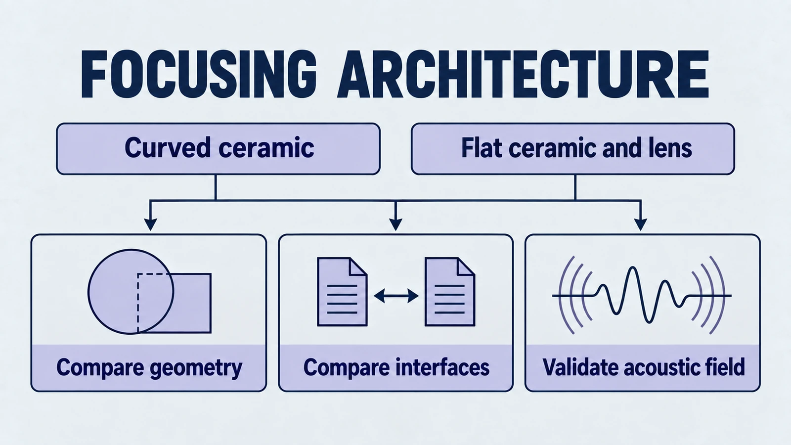
This article compares two common approaches in focused ultrasonic transducer design.
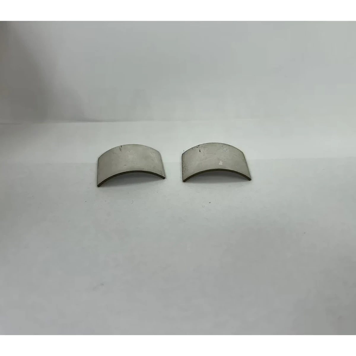
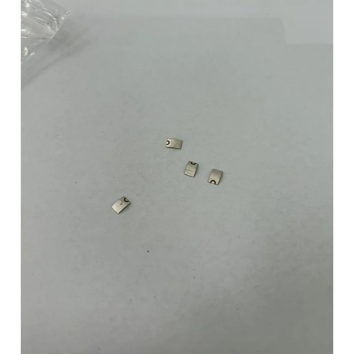
- Spherically curved (focused) piezo ceramics. The piezo element itself is the focusing surface.
- Flat piezo ceramics plus an acoustic lens. The piezo generates the wave. The lens shapes it, often in architectures built from flat piezo discs, rings, or tubes.
Product path for this search intent
Match the article topic to the right YJ Piezo product page
Use this article when the choice is not just a shape, but a material tradeoff between sensitivity, loss, coupling, stability, and operating field. For "Ceramic Geometry vs Acoustic Lenses. How Engineers Choose a Focused Ultrasonic Transduc...", the practical value is in turning the topic into a measurable selection or sourcing decision.
- PZT Material Hub
Material grades and application tradeoffs
- Piezoelectric Ceramics
Shapes and ceramic manufacturing options
- PZT Material Supplier Hub
Material control, grade selection, and sourcing support
Neither is universally superior. The “right” choice depends on what you are optimizing for. Your frequency, duty cycle, thermal headroom, coupling variability, production volume, service strategy, regulatory constraints, and how allergic your team is to alignment rework.
If you are here because your team is debating acoustic lens vs curved piezo for a new device, the goal is not to win the argument. The goal is to pick an architecture that you can manufacture, verify, qualify, and support without unpleasant surprises. For geometry context, compare how bowl-shaped piezo ceramics focus ultrasound and spherical-cap vs hemispherical design.
Use this page when the shortlist already includes focused architectures: if your team is still comparing the broader shape families, go back to the overview of piezoelectric ceramic geometries. This article is for the next decision: whether the focusing job should be handled by a curved ceramic or by a flat element with an acoustic lens.
A quick mental model. Where focusing actually happens
Focusing is the result of a phase front being shaped so that energy converges at a target region. You can shape that phase front in at least two ways.
- Geometry of the radiating surface. A curved piezo naturally launches a converging wavefront.
- A refractive element in the acoustic path. A lens changes propagation speed paths so the wavefront bends.
In practice, both methods must still deal with everything that tries to un focus your design. Bond layers. Backing impedance. Housing stiffness. Temperature drift. Medium change. Assembly stack ups. Cable strain. Moisture ingress. And the simple fact that production tolerances are not a rounding error.
A useful way to keep this grounded is to separate three “focus stories”.
- Geometric focus. What the CAD implies at nominal dimensions.
- Acoustic focus. What you measure in water tank beam mapping on a golden unit.
- Production focus. What you get across 50 or 200 units after tolerance stack up, bonding variation, and thermal cycling.
Most project failures happen because teams optimize the first two, then discover the third too late. For failure-driven geometry analysis, see mode coupling risk in piezo ceramics.
Decision framing. Start with constraints, not preferences
If you only remember one thing, remember this. You are not selecting “curved vs lens.” You are selecting which set of risks you would rather own.
A practical way to structure ultrasonic focusing method selection is to ask five questions. Teams evaluating focused elements can also review when not to use focused piezoelectric ceramics before locking architecture.
- How much acoustic efficiency can you afford to lose?
- How repeatable must the focal characteristics be across units and over time?
- How variable is your coupling medium, and how controlled is alignment in the field?
- How long must performance remain stable under duty cycle and temperature stress?
- What is your volume and service model. prototype, low volume OEM, or scaled production with replacement parts?
Add two more if you are building a commercial product.
- What does your verification plan actually measure. beam map, acoustic power, temperature rise, impedance drift, or all of the above?
- What happens when parts are replaced. can a technician swap a module without re calibration?
We will use these questions to compare architectures on the exact dimensions that usually decide real projects.
1. Acoustic efficiency and insertion losses
Acoustic efficiency is not one number. It is the combination of electromechanical conversion, acoustic radiation into the medium, and what survives all interfaces until it reaches the focal region.
Curved piezo ceramics
Typical advantage. Fewer interfaces in the focusing path.
When the ceramic is the focusing surface, you can often avoid adding an additional refractive part directly in the acoustic path. That can reduce cumulative insertion losses associated with extra layers.
But there is a catch. Most curved ceramic implementations still require.
- a bond line to a matching layer or wear plate
- a coupling interface to the medium
- sometimes a protective coating or metallization barrier
If your design needs multiple matching layers, or if your curvature forces awkward layer forming, losses can creep back in. A matching layer that is easy to apply on a flat part can become inconsistent on a curved surface unless tooling and viscosity control are strong.
Risk to watch. Bond layer thickness variability behaves like an uninvited lens.
A slightly thicker adhesive layer on a curved interface can create spatial phase errors. That error is not evenly distributed. It is geometry dependent. The result is often a widened focal spot, reduced peak intensity, or a shifted focal distance.
Secondary risk. Edge effects and parasitic modes.
Curvature and clamping can make certain edge regions see different stress and boundary conditions. That can increase coupling into unwanted modes, which shows up as extra mechanical loss and heat.
Flat piezo plus acoustic lens
Typical advantage. You can optimize each subsystem.
A flat piezo stack is well understood, easy to match, and easy to back. Then you design a lens to do one job. Shape the wavefront.
This decoupling is powerful. You can iterate lens geometry without re qualifying the piezo process. You can also choose different lens materials for different media or temperature ranges.
The cost. Every interface is an opportunity to lose energy.
Lenses bring.
- lens material attenuation
- reflection losses at lens boundaries
- bond layer losses and thickness effects
If the lens is polymer based, attenuation can be non trivial at higher frequencies or elevated temperatures. If the lens is a rigid material, impedance mismatch and reflection can dominate unless carefully managed with matching layers or surface treatments.
Risk to watch. Internal reflections and standing waves.
Lens geometries and boundaries can create secondary reflections that feed back into the piezo. This can distort impedance curves and sometimes produce local hot spots. Teams often discover this only after extended duty cycle testing.
Practical rule of thumb
- If you are pushing tight power budgets, or you cannot tolerate extra insertion loss, curved ceramics often look attractive.
- If your system can tolerate a few more loss mechanisms in exchange for manufacturability and modularity, a lens is often easier to engineer and iterate.
A useful engineering discipline here is to estimate a “loss budget” per interface. If you cannot defend where the watts went, you will have trouble scaling performance. Use repeatable piezo test methods and track drift with d33, k, and Qm trends.
2. Manufacturing tolerances and assembly repeatability
This is where many designs either become manufacturable. Or die quietly after promising prototypes.
Repeatability is not just dimensional tolerance. It is also process variation. Adhesive thickness. Cure shrinkage. Clamping pressure. Operator technique. Lot to lot material drift.
Curved piezo ceramics
Curved ceramics require manufacturing control over.
- radius of curvature (ROC)
- thickness uniformity after forming and firing
- electrode uniformity on a non planar surface
- polarization consistency
- surface quality and micro crack control
Even small ROC deviations can shift focal distance. Thickness gradients can split resonances or increase mode coupling. Handling yield can be lower. Not because ceramics are fragile in theory. Because curved thin ceramics are unforgiving to fixtures and process drift.
Repeatability pain point. Assembly stack up is harder to clamp consistently.
Bonding curved parts often requires custom tooling to control pressure distribution and adhesive squeeze out. “Looks bonded” does not mean “bond line is uniform.” Two assemblies can look identical and still differ in focal response because the adhesive distribution is different.
Inspection reality. Measuring curvature is easier than measuring the effective acoustic phase error.
You can measure ROC with mechanical or optical methods. You cannot directly measure the phase errors created by non uniform bond lines without acoustic mapping or specialized metrology. This is why curved designs often need stronger process control and more acoustic QC.
Flat piezo plus acoustic lens
Flat ceramics are manufacturable at scale with mature processes. You can control thickness, parallelism, and electrode patterns well.
The lens then becomes the tolerance driver.
- lens geometry accuracy (surface figure, thickness)
- lens placement relative to the piezo
- bond line thickness and concentricity
- alignment datum design in the housing
But here is the good news. Lens manufacturing and inspection can be treated more like a classical mechanical part. You can measure it, reject it, and replace it without scrapping the piezo element.
Repeatability advantage. Modular sub assemblies.
You can qualify the piezo stack separately from the lens. That makes process control and incoming QC easier, especially for OEM supply chains.
Hidden challenge. Lens tolerance is not just geometry. It is material properties.
A polymer lens from one lot can differ in modulus, density, or attenuation. That can change focal gain and bandwidth. If your design is sensitive, you may need material certificates or lot qualification tests.
Practical rule of thumb
- If you need high unit to unit repeatability and you want inspection friendly components, the lens approach often wins.
- If your supplier has strong curved ceramic capability and you can lock the process early, curved ceramics can be repeatable, but it is usually more supplier dependent.
A practical tactic for both architectures is to define acceptance criteria that tie manufacturing metrics to system metrics. For example. curvature and thickness ranges plus a simple acoustic test that correlates with focal peak intensity or focal distance. If you are selecting spherical-cap geometry, cross-check with radius/aperture/thickness trade-offs and ROC selection guidance.
3. Sensitivity to misalignment and medium changes
Focusing is fragile. Your focal spot is not a brick. It is a field pattern. Misalignment and medium variability distort it quickly.
Think of misalignment in three categories.
- Tilt. Angular misalignment between components.
- Decenter. Lateral offset of lens or ceramic relative to the mechanical axis.
- Standoff error. Variation in the distance from the acoustic aperture to the target region.
Then add medium changes.
- speed of sound variability with temperature and composition
- coupling layer thickness drift
- bubble formation or cavitation conditions
Curved piezo ceramics
Curved ceramics are generally sensitive to tilt and decentering, because the radiating surface itself defines the phase front. If the assembly introduces angular error, the beam can shift off axis and the focal intensity can drop.
Medium changes matter too.
- In water like media, focusing can behave predictably.
- In tissue like media, speed of sound variability can shift the effective focus.
- In air, most designs are dominated by impedance mismatch and coupling constraints.
Curved geometry does not magically solve this. It just shapes the initial wavefront.
Common integration trap. Mechanical datums do not match acoustic datums.
A housing that references the outer diameter of a ceramic does not by itself confirm the acoustic center aligns with the mechanical center. If electrode patterning or curvature is slightly asymmetric, you can get beam steering effects.
Flat piezo plus acoustic lens
A lens can be designed to reduce sensitivity to certain misalignments, but it can also introduce new ones.
- If the lens is thick and the aperture is large, decentering can create asymmetric aberrations.
- If the lens is replaceable, field assembly errors become a real risk.
Medium sensitivity can be tuned.
With lenses, you can sometimes adjust lens geometry or material choice to target a particular medium. But if your product is used across multiple media or coupling conditions, that tuning may become a liability. A lens tuned for water like media may behave differently in tissue like environments or when temperature shifts the sound speed.
Field reality. Standoff variation is often the dominant problem.
In many products, users cannot hold a constant standoff distance. In that case, you need to decide whether you want a tight focus with higher peak intensity, or a more forgiving focus with a larger depth of field. This decision affects both curved and lens based designs, but lens based architectures sometimes provide more knobs to tune that compromise.
Practical rule of thumb
- If your field setup has poor alignment control, you should prefer the architecture that is easier to fixture and reference. Often that is flat plus lens, because you can build mechanical datums around the lens housing and define a replaceable module.
- If your medium is fixed and well controlled, both can work. Then you choose based on losses, stability, and production reality.
Also. Do not rely on a single water tank beam map. Measure sensitivity. For example. beam map at nominal, then at small tilt, small decenter, and across temperature. You want slopes, not just points. In medical-style focused use cases, this is consistent with constraints discussed in focused piezo ceramics for medical ultrasound.
4. Long term stability, aging, and replacement risk
Focused systems often fail not because the focus was wrong on day one. They fail because it drifts by month six.
Long term stability is a mix of material aging, bond aging, and how hard you drive the system.
Curved piezo ceramics
Main risks.
- Piezo property drift under temperature and high drive. Changes in resonance and electromechanical coupling can shift output.
- Bond fatigue on curved interfaces. Stress distribution can be uneven.
- Crack initiation due to cyclic stress if the design operates near mechanical limits.
- Moisture ingress and electrode degradation if protective layers and sealing are not robust.
Replacement risk is often higher. If the ceramic is both the active element and the focusing surface, any damage forces replacement of the entire critical component.
Reliability nuance. Curved does not necessarily mean weaker.
A well designed curved ceramic can be robust. The issue is that stress distributions can be less intuitive. If you drive near high mechanical strain, small differences in curvature, bonding, or clamping can change where the peak stress lives. That is why accelerated life testing matters.
Flat piezo plus acoustic lens
Main risks.
- Lens material aging. Some polymers absorb moisture, creep under heat, or change modulus over time.
- Lens bond line aging. Especially if thermal cycling causes differential expansion.
- Surface wear and chemical exposure if the lens is also the wear surface.
But you gain a key advantage.
You can replace the lens without touching the piezo stack.
If your service model includes periodic replacement, or if your product is used in harsh chemical cleaning environments, modularity can save you.
Aging nuance. Polymer lenses can drift, but drift can be manageable.
If the drift is slow and predictable, you can specify replacement intervals or design the system to tolerate small focal shifts. If the drift is highly variable across units, you will have a QA problem.
Practical rule of thumb
- If you need a serviceable architecture with replaceable wear components, flat plus lens is usually easier to support.
- If your environment is stable and you prioritize minimal interfaces, curved ceramics can be robust, but only if the bonding and stress design are well controlled.
A practical recommendation. Run soak and thermal cycling tests early with acoustic verification checkpoints. Focus drift is easier to fix at architecture stage than at tooling stage. Reliability teams should also baseline with continuous-duty material selection and incoming quality criteria.
5. Cost and integration complexity at low vs medium production volumes
This is where the spreadsheet meets physics.
When teams talk about cost, they often count parts and miss the real drivers. Yield. Inspection time. Rework rate. Supplier dependence. Warranty cost. Calibration time.
Low volume and prototyping
Curved piezo ceramics
- Higher unit cost due to specialized forming, yield loss, and tooling.
- Longer lead times if the supplier has limited curved capability.
- More iteration cost. Changing ROC or thickness may require re qualification.
- Higher risk that a “small change” forces a new ceramic process window.
Flat plus lens
- You can prototype quickly. Flat ceramics are standard.
- Lens geometry can be iterated via machining, molding, or additive approaches depending on frequency and tolerances.
- More assembly steps, but those steps are often easier to tweak during development.
- Easier to explore multiple focus distances by swapping lenses while keeping the same piezo stack.
For many OEM teams, this makes lens based prototypes faster, even if the final high performance design might end up curved.
Medium volume production
At medium volumes, the picture can flip.
- Curved ceramics can become cost effective if process yield stabilizes and tooling is amortized.
- Lens systems may incur recurring costs from additional parts, assembly time, and QC steps.
Integration complexity is the hidden cost.
Lens based systems require.
- additional part sourcing
- more incoming inspection
- more assembly fixtures
- more failure modes
- sometimes more calibration steps to compensate for lens variability
Curved systems require.
- tighter supplier process control
- more complex ceramic inspection and acceptance criteria
- more dependence on one supplier’s forming capability
Supply chain risk is real engineering.
If only one supplier can reliably make your curved part, your product risk increases. If lens materials are common and multiple molders exist, lens based designs can reduce single point failure risk.
Practical rule of thumb
- If you are below medium volume and expect design iteration, flat plus lens often reduces schedule risk.
- If you have a stable design, fixed medium, and you can lock a capable supplier, curved ceramics can reduce part count and long term assembly cost.
A blunt reality. Many products start lens based because iteration speed is critical, then move to curved ceramics later if performance and BOM pressure justify a redesign.
A selection matrix. What usually pushes the decision
Use this as a decision starter, not as a verdict.
Curved piezo ceramics tend to win when
- you need high acoustic efficiency and want fewer focusing interfaces
- your coupling medium is consistent and the focus target is well defined
- you need high peak intensity and want to avoid extra attenuation in the acoustic path
- your team can control assembly tooling and bond line thickness on curved surfaces
- you can commit to supplier qualification and process locking
- you want to minimize the number of parts in the acoustic stack
Flat piezo plus acoustic lens tends to win when
- you need repeatable manufacturing with inspection friendly components
- you expect iteration. ROC and focal tuning changes are likely
- you want modular replacement or serviceable wear components
- your system architecture benefits from interchangeable lens modules
- you are sensitive to supplier dependency on curved ceramic capability
- you can accept extra insertion loss in exchange for integration flexibility
Failure patterns engineers actually see
If you have evaluated a few focused projects, these will sound familiar.
Curved ceramics. Where projects get stuck
- focal distance shifts across units due to ROC drift or bond variability
- unexpected heating at duty cycle because of mechanical losses and mode coupling
- yield problems. cracked parts during handling or assembly clamping
- performance drift after extended operation. especially when driven hard
- a great beam map in water, then disappointing performance in the actual coupling setup
Lens based systems. Where projects get stuck
- insertion loss larger than expected because interfaces were underestimated
- lens aging. focal shift after thermal cycling or long term soak
- alignment sensitivity in field assembly or maintenance
- unexpected reflections and standing waves caused by lens boundaries
- lens material choice conflicts with sterilization, cleaning agents, or environmental sealing
The point is not that either approach fails. The point is that they fail differently. Choose the failure mode you can control and detect early.
A practical selection workflow for OEM teams
This workflow mirrors how many teams make the decision without pretending they have infinite time.
- Define your non negotiables. Frequency band, aperture constraints, target focal region, allowable insertion loss, duty cycle, thermal ceiling, medium variability, and any cleaning or sterilization constraints.
- Prototype the fastest architecture first. Often flat plus lens. Not because it is best. Because it is fast to iterate and teaches you what the system actually needs.
- Measure sensitivity, not just performance. Tilt sensitivity, decenter tolerance, standoff variation, coupling variability, temperature drift, and unit to unit spread. Keep the test plan realistic. If the field will be messy, test messy.
- Separate development tests from production tests. Development tests explore physics. Production tests protect yield. You need both.
- Decide your service model early. If you will replace wear surfaces or if the system is cleaned aggressively, modular lens assemblies may reduce lifecycle cost.
- Lock the architecture when the variance story is clear. The best looking beam pattern on a golden unit is not the win. The win is the tight distribution across 100 units.
A practical note. When teams skip step 3, they often choose the wrong architecture for the field environment. They optimize peak intensity and ignore sensitivity. Then customer usage reveals drift, misalignment losses, and warranty pain. Common integration traps are documented in this OEM integration checklist.
What to ask your supplier. The questions that reveal reality
Whether you are buying curved ceramics, lenses, or both, these questions separate capable suppliers from optimistic ones.
For curved piezo ceramics
- What is your ROC tolerance capability and how do you measure it. Include sampling plan and gauge method.
- What thickness uniformity can you hold after forming and firing. Provide typical process capability, not just nominal spec.
- What is your process yield for this geometry at my thickness and aperture. Ask for realistic yield, not best case.
- How do you control electrode thickness and coverage on curved surfaces.
- How do you control polarization consistency and depoling risk at elevated temperature.
- What bond line thickness control methods do you recommend, and what fixtures do you use.
- What failure modes have you seen in similar geometries under high duty cycle.
For acoustic lens assemblies
- What is the lens material attenuation at my frequency and operating temperature range. Provide data, not only marketing descriptions.
- What are the lens geometry tolerances and how are they inspected. Include surface finish and concentricity.
- What is the bond line material, target thickness, and cure control method.
- What is the expected drift after thermal cycling and soak tests. If they cannot answer, you will have to run it.
- How does the lens behave under your cleaning and chemical exposure conditions.
- Can the lens be replaced in field without re alignment, and what datums control that.
- What incoming QC checks would you recommend for lens lot to lot consistency.
If a supplier cannot answer these with specifics, you do not have a focusing architecture yet. You have a hypothesis. Supplier discussions are more actionable when aligned to real components such as custom spherical-cap piezo ceramics and broader piezoelectric ceramic options.
Verification. How to test the choice before you commit
A good architecture decision is one you can validate with a lean but meaningful test plan.
Consider adding these checks early.
- Beam mapping at nominal and off nominal alignment. Small tilt. Small decenter. Typical standoff errors.
- Acoustic output under duty cycle. Not just a short burst. Test thermal accumulation.
- Impedance drift monitoring. Track resonance and anti resonance changes with temperature and aging.
- Thermal cycling and soak. Then re measure focus and output. Drift is the story.
- Replacement simulation. For lens based designs, swap lenses like a technician would. Measure spread.
These tests do not require perfect lab equipment. They require discipline. You want to discover whether your architecture is tolerant of reality. Tie these tests to failure root-cause review practices.
Conclusion. The right choice is the one you can manufacture, verify, and support
Choosing between acoustic lens vs curved piezo is not a debate about purity. It is a decision about system risk.
- Curved ceramics can reduce part count and interface losses, but demand tighter control of geometry and bonding on a non planar surface.
- Lens based architectures can improve modularity and manufacturing repeatability, but introduce additional insertion losses and long term material and bond aging risks.
If your team makes the decision by asking “which is better,” you will get stuck. If you make the decision by asking “which failure mode can we control, detect, and afford,” you will ship.
Related topics for deeper design work
Core geometry & focusing
- Focused ultrasonic transducer design. Practical introduction to spherically curved piezo elements.
- How bowl-shaped piezo ceramics focus ultrasound in real transducer stacks.
- Spherical-cap vs hemispherical ceramics. Why geometry assumptions fail.
- How to choose ROC for focal distance stability and tolerance robustness.
- Radius/aperture/thickness trade-offs in focused ceramics.
Reliability & validation
- When not to use focused piezoelectric ceramics in field-variable conditions.
- Engineering constraints for focused piezo systems under realistic loading.
- Mode-coupling risks from geometry and boundary conditions.
- Continuous-duty material selection for thermal and aging stability.
- Common OEM integration mistakes and how to avoid them.
- How to test and measure piezoelectric materials.
- How to quantify drift with d33, k, and Qm.
- Quality assurance framework for piezo components.
- Failure troubleshooting and prevention for piezo devices.
Product & sourcing references
- Geometry reference guide for piezoelectric ceramics.
- Ultrasonic transducer types and application mapping.
- Piezoelectric ceramics product overview.
- Spherical-cap piezo ceramics for RFQ review.
- Piezo disc components.
- Piezo ring components.
- Piezo tube components.
- Ultrasonic transducer supplier page.
- Material and property reference.
- Request engineering review for a focused ceramic project.
If you want to discuss a specific application, the fastest way to get a meaningful recommendation is to share.
- operating frequency and bandwidth target
- aperture, intended focal distance, and coupling medium
- duty cycle, drive level, and thermal constraints
- production volume and service expectations
- any cleaning, sterilization, or environmental sealing constraints
With that, you can map constraints to architecture quickly and avoid expensive prototypes that answer the wrong question.
Engineering decision notes
PZT material and ceramic selection
Use this article when the choice is not just a shape, but a material tradeoff between sensitivity, loss, coupling, stability, and operating field. For "Ceramic Geometry vs Acoustic Lenses. How Engineers Choose a Focused Ultrasonic Transduc...", the practical value is in turning the topic into a measurable selection or sourcing decision.
YJ Piezo coordinates PZT ceramic projects with manufacturing support, so material formulation, sintering, polarization, electrode process, and outgoing inspection can be reviewed against the final application.
Selection checks
- Separate sensing needs from high-power actuation needs before comparing d33 or coupling values.
- Check dielectric loss, Qm, Curie temperature, aging behavior, and operating field against the real duty cycle.
- Confirm whether the application needs standard PZT grades or a custom formulation and geometry.
Failure risks
- Choosing only the highest d33 can create heat, drift, or depolarization risk in power ultrasonics.
- A ceramic that performs well in free measurement can fail once bonded, clamped, or loaded.
- Material substitutions without batch testing can change capacitance, resonance, and system tuning.
RFQ details
- Is the part used for sensing, actuation, atomization, cleaning, welding, or measurement?
- What field strength, temperature, duty cycle, and mechanical load will the ceramic see?
- Which values must be controlled: d33, capacitance, resonance, impedance, Qm, or dimensional tolerance?
Relevant YJ Piezo pages
- PZT Material Hub
Material grades and application tradeoffs
- Piezoelectric Ceramics
Shapes and ceramic manufacturing options
- PZT Material Supplier Hub
Material control, grade selection, and sourcing support
Application FAQ
- Is the highest d33 always the best PZT choice?
- No. High d33 can be useful for sensitivity, but high-power ultrasonic systems often need lower loss, higher Qm, better thermal stability, and safer operation under field and stress.
- What makes PZT material selection different from catalog buying?
- The right PZT choice depends on geometry, load, drive field, duty cycle, temperature, and inspection targets. A catalog value is only useful when it is tied to the final assembly conditions.