
Disc vs Ring vs Tube Piezo Ceramics: Geometry Trade-offs Explained
1. Introduction: The Geometric Determinism of Electro-Ceramics
In the domain of electromechanical transduction, the selection of the piezoelectric ceramic element is frequently reduced to a choice of material formulation—typically a decision between "soft" lead zirconate titanate (PZT) for high sensitivity or "hard" PZT for high power handling. While the material's intrinsic properties, such as the piezoelectric charge coefficient () or the mechanical quality factor (), establish the theoretical ceiling of performance, it is the macroscopic geometry of the ceramic that defines the realizable engineering envelope. The geometry—whether a monolithic disc, a central-bore ring, or a thin-walled tube—acts as a mechanical filter, determining which vibration modes are accessible, how the acoustic impedance matches the load, and, crucially, how the element manages the intense mechanical and thermal stresses inherent to dynamic operation.
For engineers tasked with designing ultrasonic transducers, precision actuators, or hydroacoustic sensors, the geometry is not merely a packaging constraint but an active variable in the coupled wave equation. The transition from a simple 1D piston approximation to a 3D continuum reality reveals that geometric parameters such as aspect ratio (), wall thickness, and electrode configuration fundamentally alter the resonant spectrum. A disc designed without regard for diameter-to-thickness ratios may exhibit chaotic mode coupling that renders it useless for precision timing. Conversely, a tube geometry can exploit orthogonal stress vectors to achieve hydrostatic sensitivities impossible in bulk shapes.
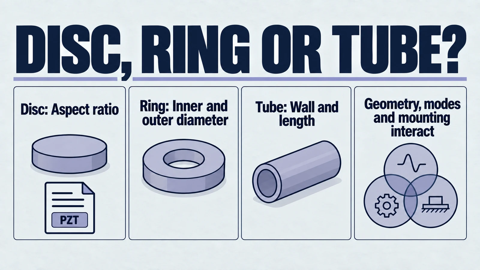
This report provides an exhaustive analysis of the three primary piezoelectric geometries: the disc, the ring, and the tube. It synthesizes classical plate theory, finite element analysis (FEA) data, and practical transducer design principles to establish a rigorous decision framework. By referencing the underlying physics of resonance modes, stress concentration, and electromechanical coupling, this document serves as a practical guide for teams choosing among the main round piezoelectric geometries. If you still need the broader shape landscape, see the geometry selection guide.
Product path for this search intent
Match the article topic to the right YJ Piezo product page
Use this article when the choice is not just a shape, but a material tradeoff between sensitivity, loss, coupling, stability, and operating field. For "Disc vs Ring vs Tube Piezo Ceramics: Geometry Trade-offs Explained", the practical value is in turning the topic into a measurable selection or sourcing decision.
- PZT Material Hub
Material grades and application tradeoffs
- Piezoelectric Ceramics
Shapes and ceramic manufacturing options
- PZT Material Supplier Hub
Material control, grade selection, and sourcing support
Use this page when the shortlist is already round: if you still need a broader comparison across rectangular, round, and focused geometries, start with the geometry selection guide. Then come back here to resolve the narrower disc vs ring vs tube trade-off.
2. Theoretical Framework: Constitutive Limits and Boundary Conditions
To understand why geometry dictates performance, one must examine the piezoelectric constitutive equations through the lens of boundary conditions. The piezoelectric effect is inherently anisotropic; the response is tensor-based, linking a vector electric field to a tensor strain field.
2.1 The Tensor Nature of Performance
The linear behavior of a piezoelectric ceramic is governed by the coupled equations of state, here expressed in the strain-charge form:
Where is strain, is stress, is electric field, is electric displacement, is compliance, is the piezoelectric coefficient, and is permittivity.
Geometry imposes the boundary conditions that zero out specific stress or strain terms, thereby selecting which material constants are active.
- The Rod Limit (): In a cylinder where length diameter, the lateral surfaces are stress-free (). The material is free to contract laterally via the Poisson effect. This condition utilizes the full compliance and typically yields the highest electromechanical coupling factor () for PZT materials.
- The Disc Limit (, ): In a thin disc where diameter thickness, the lateral dimensions are effectively clamped by the inertia of the surrounding material relative to the high-frequency thickness oscillation. This inhibits Poisson contraction, stiffening the material () and reducing the effective coupling () compared to the rod.
Aspect ratio and boundary conditions affect the effective coupling of a selected mode. A difference between thickness coupling k_t and longitudinal rod coupling k_33 is not a measurement of loaded-device power efficiency. Compare losses, loading and acoustic output separately.
2.2 Frequency Constants and Resonance Scaling
Resonance describes the condition where the mechanical dimensions of the ceramic support a standing wave. The frequency of this resonance () scales inversely with the governing dimension, a relationship quantified by the Frequency Constant ().
| Mode | Governing Dimension | Frequency Constant () | Typical Value (PZT-4/8) |
|---|---|---|---|
| Longitudinal | Length () | 1600 Hz·m | |
| Transverse/Radial | Diameter () | (Planar) | 2000 - 2200 Hz·m |
| Thickness | Thickness () | 2000 Hz·m | |
| Shear | Thickness () | 1000 Hz·m |
The proximity of these resonances is the primary geometric hazard. A ceramic element has multiple dimensions (e.g., a disc has both and ). If the dimensions are selected such that , the modes will couple. This coupling is not merely a superposition; it involves a sophisticated energy exchange that distorts the mode shapes, creates non-uniform surface displacements, and generates impedance anomalies.
3. The Piezoelectric Disc: The Problem of Aspect Ratio
The piezoelectric disc is the most ubiquitous geometry, serving as the active element in sensors, buzzers, and high-frequency medical ultrasound probes. However, it is also the geometry most susceptible to complex mode coupling, particularly when the aspect ratio falls into the "forbidden zone."
3.1 The Spectrum of Vibration
Research into the vibration of discs has classified the vibration spectrum into distinct families of modes:
- Thickness Extensional (TE) Mode: This is the desired "piston" motion for ultrasound generation. The disc expands and contracts uniformly in the -direction.
- Radial (R) Modes: These are contour modes where the disc expands and contracts radially. The fundamental R-mode is the lowest frequency resonance of a thin disc.
- Edge (E) Mode: This is a specialized mode where vibrational energy is localized at the periphery of the disc. It is largely independent of the diameter-to-thickness ratio but can cause significant acoustic sidelobes.
- High-Frequency Radial (A) Modes: These are higher-order radial harmonics that appear at frequencies near the thickness resonance.
3.2 The "Forbidden Zone": Diameter-to-Thickness Ratio 3 to 6
The interaction between the Radial (R) modes and the Thickness (TE) mode is strictly governed by the Diameter-to-Thickness () ratio.
- Thin Disc: Large diameter-to-thickness ratio can support a useful thickness-mode approximation over a selected frequency interval. Finite boundaries and higher modes remain; a ratio above 10 is not a universal clean-spectrum or piston-motion guarantee.
- The Rod Region (): Here, the element is a cylinder. The longitudinal mode dominates, and the radial modes are pushed to much higher frequencies. This region is also spectrally clean.
- Mode Interaction: Aspect ratio shifts radial, edge and thickness branches. Identify crossings, drive overlap and the assembled mode shapes for the actual material and boundaries; 3–6 is not a universal forbidden interval.
Consequences: The mode coupling is strong. The element does not vibrate as a piston; instead, the surface displacement becomes wavy or non-uniform. The impedance curve exhibits "split" peaks or jaggedness, making it difficult for drive electronics to maintain a lock on resonance.
Engineering Recommendation: Evaluate the geometry’s relevant mode branches using impedance measurements, mode-shape measurements and a validated model. Change geometry, electrodes, backing or loading when the identified unwanted response matters; a universal aspect-ratio ban or mandatory composite conversion is not supported.
3.3 Power Limitations of the Disc
While geometrically simple, the disc is mechanically compromised for high-power applications. PZT ceramics are brittle materials with a dynamic tensile strength limited to approximately 20–25 MPa. In a high-power drive scenario, the sinusoidal excitation creates alternating compressive and tensile stresses.
- Tensile Stress: A free ceramic disc can develop alternating stress under resonant drive. Solid actuators can also be externally preloaded; predict the assembled stress field and qualify strength/defects rather than assuming the absence of a central hole makes preload impossible.
- Thermal Constraints: Heat generation in PZT is driven by dielectric loss () and mechanical damping (). In a solid disc, the thermal path from the center of the ceramic to the periphery is long and conductive resistance is high. Under continuous wave (CW) high-power operation, the core temperature can rise significantly, leading to property shifts or thermal depolarization.
Discs can operate in continuous-wave high-power systems when the material, mounting, preload where applicable, acoustic load and cooling are designed and validated together. A ring provides a convenient central bolt path but is not the only geometry capable of continuous operation. Review the actual duty and mounting requirements for ultrasonic cleaning.
4. The Piezoelectric Ring: The Architecture of Power
The ring (or annular) geometry addresses the fundamental mechanical limitations of the disc. By introducing a central bore, the ring enables the construction of the Bolt-Clamped Langevin Transducer (BLT), the standard architecture for high-power ultrasonics.
4.1 The Physics of Pre-stress
The defining advantage of the ring geometry is the ability to apply a static compressive bias. By stacking PZT rings and clamping them with a central high-strength bolt between metal masses (the front driver and back mass), the ceramic is placed under significant pre-stress.
Mechanism of Action:
Consider a PZT-8 ring with a dynamic tensile limit of 25 MPa and a compressive limit >500 MPa.
- Without Pre-stress: The maximum allowable dynamic stress amplitude is ~25 MPa.
- With Pre-stress (e.g., 40 MPa): The ceramic is biased at -40 MPa. A dynamic oscillation of MPa results in a stress excursion from -75 MPa (compression) to -5 MPa (compression).
Result: The material never enters the tensile regime. The operational ceiling is effectively doubled or tripled, limited now only by the depolarization field or the mechanical losses rather than fracture.
Optimal Pre-stress Levels:
- PZT-4 (Hard): Recommended pre-stress is typically 35 MPa.
- PZT-8 (Extra Hard): Can sustain higher pre-stress, typically 45 MPa.
Over-stress Risks: Excessive pre-stress (>60-80 MPa) suppresses the domain wall motion, effectively "clamping" the dipole reorientation. While this increases mechanical , it reduces the effective and coupling factor, eventually leading to a drop in performance or crushing failure.
4.2 Vibration Modes of the Ring
The ring geometry possesses its own unique set of vibration modes, distinct from the disc.
- Hoop Mode: The fundamental radial resonance of a ring is the "hoop" or "breathing" mode, where the mean circumference expands and contracts. Unlike the radial mode of a disc, which has a node at the center, the hoop mode has no radial node within the ceramic cross-section (assuming thin walls). This mode is often utilized in underwater sonar projectors.
- Thickness Mode in Stacks: In a Langevin transducer, the resonance frequency is determined by the entire assembly (mass-spring-mass system), not the thickness of the individual rings. The rings act primarily as the driving spring. This allows the use of relatively thin rings (e.g., 5-10 mm) to construct low-frequency (20-40 kHz) transducers, decoupling the ceramic manufacturing thickness limits from the operating frequency.
4.3 Inner-to-Outer Diameter (ID/OD) Ratios
The ratio of the inner diameter (ID) to the outer diameter (OD) is a critical design variable affecting both electromechanical coupling and stress distribution.
- Coupling Efficiency (): Research suggests that rings can exhibit higher effective electromechanical coupling factors than solid discs for radial modes. The removal of the central material (which contributes mass but little active generation in radial modes) improves the energy density.
- Stress Distribution: In a bolt-clamped stack, the static pressure applied by the bolt is not uniform across the face of the ring. FEA and pressure-film checks often show higher stress near the ID (under the bolt head), with stress decaying toward the OD.
- Design Risk: If the ring is too wide (small ID/OD ratio), the outer periphery may see insufficient pre-stress. During high-amplitude vibration, the outer edges may effectively "lift off" or experience tension, leading to edge chipping or arcing.
Optimization: The ring dimensions should be matched to the bolt and mass footprint to ensuring the entire ceramic surface remains under compression.
4.4 Thermal Management Advantages
Rings offer superior thermal management compared to discs, a necessity for high-power operation.
- Conductive Cooling: The metal end-masses (aluminum front, steel back) act as large heat sinks, drawing heat away from the ceramic faces.
- Geometric Surface Area: The central bore increases the surface area available for convection (if forced air is used).
- Modular Cooling: In extreme power applications, thin Beryllium-Copper cooling fins can be inserted between the PZT rings in the stack, a geometric modification impossible with monolithic blocks.
5. The Piezoelectric Tube: Radial, Hydrostatic, and Bending Modes
The tube geometry (cylindrical shell) introduces a high degree of versatility, enabling modes of operation—such as hydrostatic sensing and multi-axis bending—that are inaccessible to discs or rings. However, this versatility comes with complex impedance characteristics and structural fragility.
5.1 Vibration Modes and Wall Thickness
Tubes generally operate in one of three primary modes, selected by the polarization and electrode configuration.
- Radial Breathing Mode: The entire tube expands and contracts in diameter. The frequency is governed by the mean diameter () and the material sound speed (). This mode is widely used in hydrophones and fluidic pumps.
- Length (Longitudinal) Mode: The tube extends and contracts axially. This uses the coefficient (transverse effect) if the tube is radially polarized.
- Wall Thickness Mode: At high frequencies, the wall itself resonates. The frequency is determined by the wall thickness () and the thickness frequency constant ().
5.2 Hydrostatic Sensitivity () and Polarization Strategy
The tube is the geometry of choice for underwater sensors (hydrophones) because it can be engineered to overcome the "hydrostatic cancellation" problem of bulk PZT.
The Problem: In a bulk solid under hydrostatic pressure, stress is isotropic (). The charge generated is proportional to . Since pC/N and pC/N, the terms nearly cancel ( pC/N), resulting in poor sensitivity.
Geometric Solutions:
- Air-Backed Radially Polarized Tube: External pressure produces hoop stress and, when pressure acts on closed ends, axial stress transmitted through the end structure. Radial stress also varies through the wall, from the external pressure boundary to the internal boundary. Thin-shell estimates can neglect radial stress relative to amplified membrane stresses under specified conditions; they do not make all stresses vanish along the poling axis. Model the actual caps, supports, thickness and electrode/poling arrangement.
- Tangentially Polarized Tube: An advanced technique involves applying stripe electrodes to pole the ceramic circumferentially (tangentially). In this configuration, the large hoop stress acts along the poling axis ( effect), while the axial and radial stresses act transversely ( effect). Because the hoop stress is geometrically amplified by the radius-to-thickness ratio (), this configuration yields exceptionally high hydrostatic sensitivity (), often orders of magnitude higher than bulk cylinders.
5.3 Bending and Scanning (The AFM Application)
Tubes are also uniquely capable of multi-axis actuation. By segmenting the outer electrode into four quadrants (), a tube can be made to bend.
- Mechanism: Opposite quadrant drives produce different axial strains through d_31. For the usual negative d_31, a radial field aligned with the poling direction produces axial contraction; reversing the field produces expansion within the permitted drive range. Specify the voltage reference and poling direction before assigning a quadrant’s motion.
- Coupling: This bending mode often couples with the fundamental length extension (-axis). Correcting for this "cross-talk" or "run-out" is a major challenge in Atomic Force Microscopy (AFM) scanner design. The tube geometry offers high stiffness-to-weight ratio, allowing for high-bandwidth scanning frequencies that are difficult to achieve with bimorph benders.
5.4 Mechanical Fragility and Hoop Stress Limits
The structural Achilles' heel of the tube is its susceptibility to tensile hoop stress.
- Internal Pressurization: In fluidic applications (e.g., inkjets), internal pressure creates tensile hoop stress . Tensile limits depend on grade, flaws, waveform, temperature and assembly. Evaluate local hoop stress against qualified strength/fatigue data; an unqualified 25 MPa value is not a universal dynamic limit.
- Defect Sensitivity: Any micro-crack on the end face (from cutting or grinding) acts as a stress concentrator. Under radial resonance, these cracks propagate instantly along the length.
- Depolarization under Pressure: For deep-sea applications, the immense external hydrostatic pressure creates compressive hoop stress. While this prevents tensile failure, excessive stress can reorient domains, leading to permanent sensitivity loss.
6. Materials Selection in Context: The Geometry-Material Matrix
The choice of PZT formulation (Hard vs. Soft) cannot be made in isolation from the geometry.
6.1 PZT-8 vs PZT-4 in Rings (Power)
For Langevin ring stacks, the industry standard is "Hard" PZT. However, the distinction between PZT-4 and PZT-8 is nuanced.
- PZT-8 (Navy Type III): This material has the lowest dielectric loss and highest mechanical . It is the preferred choice for high-power, continuous-duty applications like ultrasonic welding or high-intensity focused ultrasound (focused ultrasound). Allowable preload and power density require exact-grade/assembly measurements and stress, field, temperature and lifetime conditions; 45 MPa is not a universal safe preload.
- PZT-4 (Navy Type I): While still a "hard" material, PZT-4 has slightly higher losses but often higher and coupling than PZT-8. It is frequently used in medium-power applications like ultrasonic cleaning tanks, where the duty cycle is intermittent, or in transmit/receive sonar where sensitivity is slightly more valued.
6.2 Soft PZT (PZT-5A/5H) in Tubes and Discs (Sensing/Actuation)
Tubes (Scanners/Hydrophones): Soft PZT is almost exclusively used here.
- Reason 1 (Scanners): High is required to maximize the bending deflection per volt. The high hysteresis of soft PZT is managed via closed-loop control.
- Reason 2 (Hydrophones): High (voltage constant) is critical for receiving weak signals. Open-circuit voltage depends on g = d/ε, geometry and loading; higher permittivity alone does not improve voltage sensitivity or SNR. Evaluate the actual noise and readout model.
Discs (NDT): PZT-5H is the standard for pulse-echo NDT probes due to its high coupling (), which correlates to broad bandwidth and short pulse ring-down (when heavily damped).
6.3 Material Data Comparison
The following table highlights how material properties must be matched to geometry and application stress limits.
| Parameter | PZT-4 (Hard) | PZT-8 (Hard) | PZT-5A (Soft) | Implications for Geometry |
|---|---|---|---|---|
| (pC/N) | ~300 | ~220 | ~400 | Soft PZT tubes bend more; Hard PZT rings generate less heat. |
| 0.70 | 0.64 | 0.71 | High coupling in PZT-4/5A aids broad bandwidth in discs. | |
| ~500 | ~1000 | ~75 | High of PZT-8 essential for resonance in rings. Low of PZT-5A aids damping in NDT discs. | |
| Max Pre-stress | ~35 MPa | ~45 MPa | N/A | PZT-8 rings can be clamped harder for higher power output. |
| Curie Temp () | ~320°C | ~300°C | ~360°C | High generally preferred for stability, but Soft PZT allows lower temp processing. |
| Loss () | 0.4% | 0.2% | 2.0% | High loss in Soft PZT tubes causes self-heating if driven continuously. |
7. Comparative Analysis and Decision Framework
The selection of geometry should follow a logical flow based on the primary constraints of the application: Power, Sensitivity, and Directionality.
7.1 Geometry Selection Matrix
| Design Goal | Preferred Geometry | Engineering Rationale | Critical Constraint |
|---|---|---|---|
| High Power Generation (Welding, Cleaning) | Ring (Langevin Stack) | Enables bolt-clamped pre-stressing to prevent tensile fracture. Large thermal mass. | Uniform clamping pressure ( ratio). |
| High Frequency Sensing (>1 MHz, NDT) | Disc | Simple fabrication, clean thickness mode if aspect ratio is controlled. | Validate the mode spectrum for the actual aspect ratio, material and assembled boundaries. |
| Hydrostatic Sensing (Sonar) | Tube (Air-backed) | Geometric decoupling of and prevents cancellation. | Wall thickness limits crush depth. |
| Precision Actuation (AFM, Fiber align) | Tube | Orthogonal bending and extension modes in one element. High stiffness. | Fragility; coupling between X/Y/Z axes. |
| Omnidirectional Source | Sphere/Tube | Radial breathing mode provides isotropic radiation pattern (in plane). | Manufacturing complexity; cost. |
7.2 The "Forbidden Zone" Checklist
Before finalizing a disc or ring design, the engineer must validate the aspect ratio.
- Record diameter, thickness, material and the relevant electrical/mechanical boundaries.
- Estimate radial and thickness branches with the appropriate frequency constants; do not treat a numerical ratio alone as proof of a pure mode.
- Check the measured spectrum and mode shapes under the intended load. Nearby frequencies or integer relations alone do not prove coupling; symmetry and overlap matter.
7.3 Thermal and Electrical Safety
Voltage Limits:
- Discs: Limited by dielectric breakdown (typ. 2-3 kV/mm).
- Tubes: Limited by wall thickness. A 1mm wall tube reaches breakdown voltage at only ~2-3 kV, limiting total drive power.
- Rings: Electrically parallel-connected layers receive the same terminal voltage; parallel wiring does not divide it among layers. Series wiring divides voltage according to individual impedances. Specify the circuit, per-layer field, insulation and drive limits; do not infer safety from stack geometry.
Duty Cycle:
- Continuous (CW): Qualify the material, shape, drive, mechanical/acoustic load and thermal path for sustained operation. PZT-8 rings are one useful architecture, not a universal requirement.
- Pulsed: Qualify peak field/stress, repetition rate, duty and thermal behavior. Off-time can reduce average heating, but does not automatically make a selected disc or tube safe.
8. Conclusion: Geometry as the Primary Design Variable
Each shape offers engineering tradeoffs. Discs, rings and tubes all require qualified materials, stress limits, mode control and thermal paths. A ring is convenient for a central bolt-clamped stack; solid discs can also serve continuous-power designs, and externally preloaded solid actuators exist. Tubes provide useful radial and bending modes, with behavior dependent on their electrodes, supports and load.
Ultimately, the successful integration of piezoelectric ceramics requires moving beyond the datasheet values of and . It demands a holistic view where the material properties are seen as potentials that are only realized—or squandered—by the geometry of the element. By respecting the physics of aspect ratios, stress concentrations, and mode coupling, engineers can design transducers that not only survive but thrive in their intended applications.
Engineering decision notes
PZT material and ceramic selection
Use this article when the choice is not just a shape, but a material tradeoff between sensitivity, loss, coupling, stability, and operating field. For "Disc vs Ring vs Tube Piezo Ceramics: Geometry Trade-offs Explained", the practical value is in turning the topic into a measurable selection or sourcing decision.
YJ Piezo coordinates PZT ceramic projects with manufacturing support, so material formulation, sintering, polarization, electrode process, and outgoing inspection can be reviewed against the final application.
Selection checks
- Separate sensing needs from high-power actuation needs before comparing d33 or coupling values.
- Check dielectric loss, Qm, Curie temperature, aging behavior, and operating field against the real duty cycle.
- Confirm whether the application needs standard PZT grades or a custom formulation and geometry.
Failure risks
- Choosing only the highest d33 can create heat, drift, or depolarization risk in power ultrasonics.
- A ceramic that performs well in free measurement can fail once bonded, clamped, or loaded.
- Material substitutions without batch testing can change capacitance, resonance, and system tuning.
RFQ details
- Is the part used for sensing, actuation, atomization, cleaning, welding, or measurement?
- What field strength, temperature, duty cycle, and mechanical load will the ceramic see?
- Which values must be controlled: d33, capacitance, resonance, impedance, Qm, or dimensional tolerance?
Relevant YJ Piezo pages
- PZT Material Hub
Material grades and application tradeoffs
- Piezoelectric Ceramics
Shapes and ceramic manufacturing options
- PZT Material Supplier Hub
Material control, grade selection, and sourcing support
Application FAQ
- Is the highest d33 always the best PZT choice?
- No. High d33 can be useful for sensitivity, but high-power ultrasonic systems often need lower loss, higher Qm, better thermal stability, and safer operation under field and stress.
- What makes PZT material selection different from catalog buying?
- The right PZT choice depends on geometry, load, drive field, duty cycle, temperature, and inspection targets. A catalog value is only useful when it is tied to the final assembly conditions.