
Troubleshooting Piezo Devices: Common Failures and How to Prevent Them
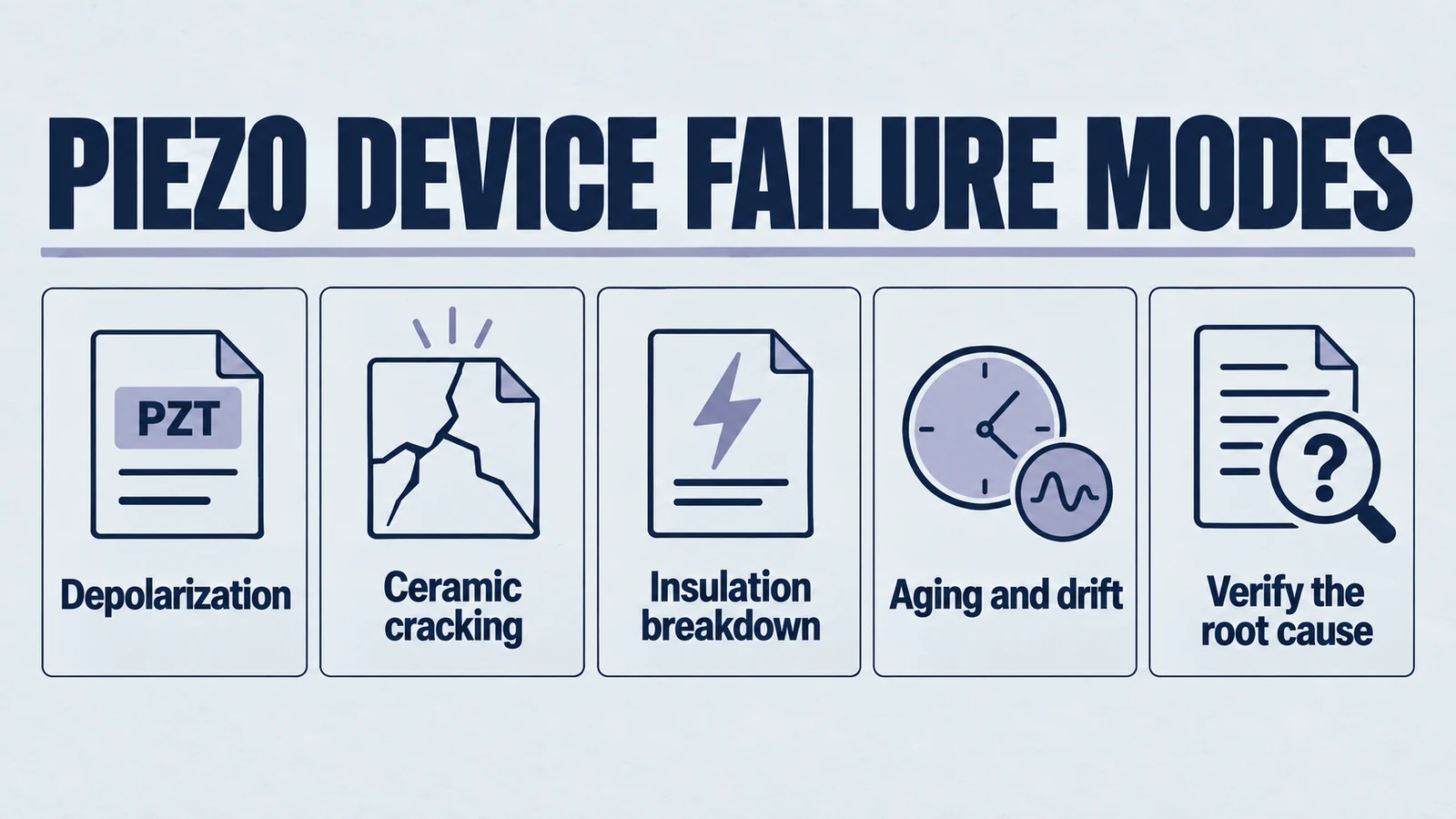
A piezo device that loses output, runs hot, or shifts resonance does not automatically have a damaged ceramic. Start by separating the driver, wiring, mounting, and operating load from the piezo element. Compare measurements with an accepted unit or a recorded baseline under the same conditions before deciding to replace it.
This guide covers bare PZT elements and piezo assemblies used in sensing, actuation, and ultrasonics. Product-specific limits take priority: a bare disc, bonded plate, multilayer actuator, and bolt-clamped transducer do not share one voltage, temperature, or preload limit.
Start with the symptom
Use the table to choose the first checks. Each observation narrows the investigation; none is proof of a single failure mechanism.
| Symptom | Check first | What the result means | Next action |
|---|---|---|---|
| No output or much lower output | Inspect leads and electrodes; check the driver waveform at the connected load using appropriately rated equipment. | A normal control setting does not prove the device receives the intended voltage. Wiring faults or driver current limits can resemble ceramic failure. | Resolve the electrical path first, then compare output with an accepted assembly at the same load. |
| Excessive heating | Record temperature rise, waveform, voltage, frequency, duty cycle, and mechanical or acoustic load. | Heating may involve dielectric loss, mechanical loss, a poor connection, or unsuitable operating conditions. | Stop if the component exceeds its rated limits. Review drive and load conditions before another powered test. |
| Resonance shifts after assembly | Compare impedance sweeps before and after bonding, clamping, or loading, at the same temperature. | Assembly constraints change the response. A shifted peak alone does not identify a crack or depolarization. | Review fixture alignment, adhesive cure, preload, and the intended loaded resonance. |
| Intermittent output or mechanical noise | Inspect connections, electrode damage, bonding interfaces, and visible cracks without disturbing the assembly. | Several electrical and mechanical faults can create similar symptoms. | Isolate the suspect part for inspection; retain photos and test records before disassembly. |
| Leakage or insulation failure | Inspect contamination and moisture; measure insulation using the supplier-approved voltage, duration, and connections. | Low insulation can involve the ceramic, surface, wiring, or encapsulation. | Do not increase drive voltage to compensate. Separate the assembly paths and seek a controlled failure review. |
| Slow drift in sensitivity or displacement | Repeat the baseline after temperature stabilization; check load, drive, elapsed time, and measurement setup. | Temperature, aging, mounting changes, and damage must be distinguished. | Trend multiple measurements rather than rejecting the part from one reading. |
Measure under comparable conditions
Log the instrument, fixture, test frequency, signal amplitude, temperature, and whether the part is free, bonded, or clamped. Include DC bias where applicable. PI's electrical-operation guidance explains why small-signal capacitance differs from behavior under operating voltage, temperature, and mechanical load.
- Capacitance and dielectric loss: compare at the same specified test conditions, with the driver disconnected. Do not compare readings from different meter frequencies as if they were equivalent.
- Impedance and resonance: save the curve, sweep range, signal level, fixture, and load, not just one peak frequency. A free-element measurement is not the acceptance test for a completed transducer.
- Insulation resistance: use the component's approved test procedure. A generic high-voltage insulation test can damage a part that was not designed for it.
- Displacement or acoustic output: retain the drive waveform and measurement geometry. Compare output only under equivalent mechanical or acoustic conditions.
For setup details, see testing and measuring piezoelectric materials. Use the purchase specification or an agreed baseline for acceptance limits; this guide does not impose a universal percentage tolerance.
Distinguish the main failure mechanisms
Depolarization
Excessive temperature, an unsuitable reverse field, or excessive mechanical stress can affect polarization. The Curie temperature is not a recommended operating temperature. Check the actual material and assembly limits, including soldering and adhesive-cure conditions. PI Ceramic's piezo component handling manual discusses thermal depolarization and assembly precautions.
Reduced output is a reason to investigate, not a diagnosis. Rule out wiring, driver, load, and temperature differences first. A capacitance change by itself does not confirm depolarization, and adding voltage is not a repair.
Cracks, bonding defects, and mounting stress
Inspect edges, electrodes, adhesive joints, and load alignment. PI Ceramic's forces and stiffness guidance describes the sensitivity of brittle piezo actuators to tensile and lateral loading. Use the assembly's specified preload and support geometry; do not transfer a preload value from a different actuator or transducer design.
A resonance change after bonding may be an expected assembly effect. Persistent changes together with visible damage or abnormal output justify further inspection. A normal visual check does not exclude internal damage.
Insulation damage and moisture
Check surface contamination, cable insulation, connectors, and sealing before attributing leakage to the ceramic bulk. PI's ambient-conditions guidance describes how humidity and sustained electrical bias can affect actuator reliability. Moisture-related leakage should not be treated as direct proof of depolarization.
Record environmental exposure and isolate suspect parts. Drying or cleaning must follow an approved process; a temporarily improved reading does not establish that a damaged assembly is reliable again.
Aging, temperature effects, and drift
PZT properties depend on material and conditions. PI Ceramic's material guidance includes temperature-dependent capacitance, resonance, coupling, and charge coefficients. Measure after stabilization and compare with the same material, geometry, and assembly state. Do not label every gradual output change as aging, or every change in bandwidth as permanent damage.
A practical isolation sequence
- Make the assembly safe. Disconnect power and discharge stored charge using the equipment manufacturer's procedure before handling connections. Stop testing a cracked, arcing, or overheating assembly.
- Capture the failure. Record when it began and whether it follows a temperature, duty-cycle, driver, mounting, or material change.
- Check the external system. Verify cables, contacts, driver settings, and actual load conditions before removing or replacing the ceramic.
- Compare controlled measurements. Repeat capacitance, loss, impedance, and appropriate output measurements against an accepted baseline.
- Change one variable. If compatible and safe, compare a known-good component in the same fixture, or the suspect component in a qualified setup. Keep drive and load conditions fixed.
- Confirm the correction. Repeat the relevant operating cycle within rated limits and document the result. One successful low-power test does not qualify the complete application.
Prevent a repeat failure
Choose the corrective action from the evidence: restore a damaged connection, correct the drive conditions, revise mounting or bonding, improve environmental protection, or review the ceramic specification. Keep incoming measurements and assembled-system acceptance tests separate. For power ultrasonics, use the ultrasonic transducer troubleshooting guide alongside the system's operating instructions.
Send the right information for an engineering review
If you need help reviewing a YJ Piezo component or selecting a replacement, send:
- Part number or drawing, material grade if known, dimensions, batch reference, and affected quantity.
- Application, mounting or bonding arrangement, and photos of the complete assembly and suspect area.
- Drive voltage with peak, peak-to-peak, or RMS clearly identified; frequency, waveform, DC offset, and duty cycle.
- Temperature, humidity or liquid exposure, mechanical load, and time to failure.
- Baseline and failed-unit measurements, including the instrument and test conditions.
Discuss your piezo component with YJ Piezo. Include replacement quantity or annual demand if you also need a quotation. Failure assessment and replacement suitability depend on the supplied evidence and application review.
External References
The linked manufacturer resources explain general piezo behavior and measurement considerations. Their product-specific ratings do not establish limits for a YJ Piezo component; use its agreed specification and assembly requirements.