
Custom Piezo Ring Engineering for OEM Programs: From Spec to Validated Prototype
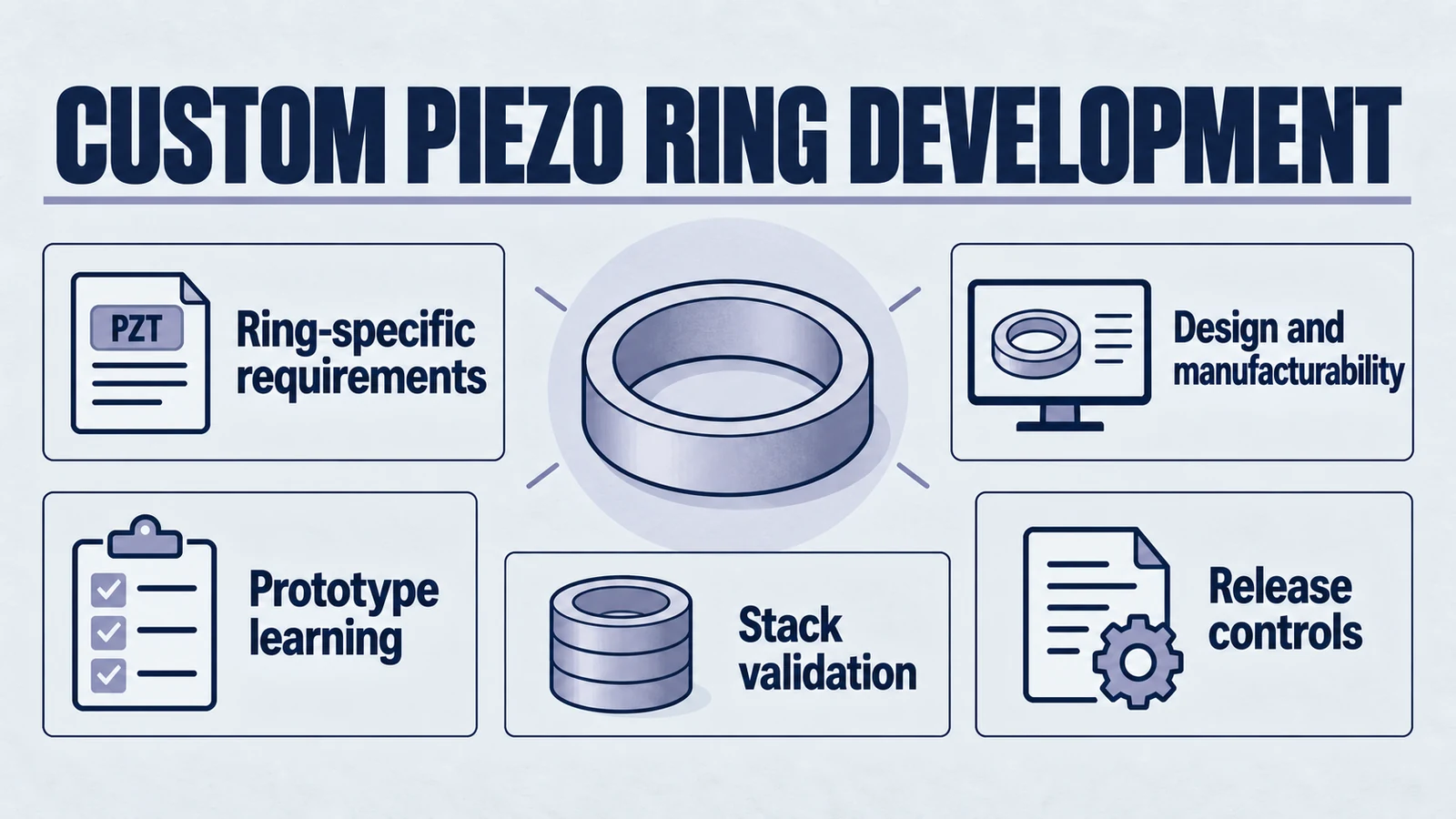
Not every OEM program needs a custom ring. But when the application depends on preload stability, stack architecture, thermal behavior, or a specific acoustic envelope, a generic catalog ring often becomes the bottleneck. This page is for the moment after the team has already narrowed the shape family to piezoelectric rings and needs to turn that choice into a validated engineering path.
If your team is still comparing rings against discs, tubes, rectangular plates, or focused geometries, go back to our geometry selection guide. If the geometry is already decided but procurement needs a sourcing and QA framework, use our ring procurement guide. This page sits between those two decisions: it focuses on custom ring engineering and OEM co-development.
1. When ring geometry becomes the right branch
Rings are often selected because the application needs more than “a round ceramic.” The center opening changes the mechanical system. It creates room for bolts, shafts, fluid paths, or central structures. It also makes pre-stressed stack architectures practical, which is why rings appear so often in high-power ultrasonic systems.
Product path for this search intent
Match the article topic to the right YJ Piezo product page
Use this article when the risk is supplier selection, engineering support, validation evidence, integration reliability, and whether the manufacturer can scale from sample to production. For "Custom Piezo Ring Engineering for OEM Programs: From Spec to Validated Prototype", the practical value is in turning the topic into a measurable selection or sourcing decision.
- Ultrasonic Transducer Supplier Hub
OEM sourcing and engineering collaboration
- PZT Material Supplier Hub
Material control and grade selection
- Piezoelectric Ceramics
Ceramic manufacturing and custom shapes
In OEM development, ring geometry usually enters the shortlist for one or more of these reasons:
- Preload matters: the design needs a mechanically compressed stack to protect the ceramic under high dynamic drive.
- Thermal behavior matters: continuous-duty ultrasonic systems need a geometry that can live inside a robust transducer assembly.
- Integration matters: the package needs a central aperture for bolts, shafts, wires, or fluidic channels.
- Power density matters: the program is building a welding, cleaning, sonar, or other high-energy acoustic stack.
That does not mean all ring projects are the same. Once the ring branch is chosen, the real engineering work is deciding what kind of ring system the application actually needs.
2. Custom ring engineering starts by translating the application into ring-specific inputs
OEM teams often describe the problem at product level: “we need more amplitude,” “the stack runs hot,” “the output drifted after endurance,” or “the assembly cannot fit the current transducer.” Those are valid symptoms, but a supplier cannot engineer the right ring from symptoms alone. The application has to be translated into ring-specific design inputs.
The custom ring brief should cover:
- OD, ID, and thickness targets, including which dimensions are driven by acoustics and which by mechanical integration.
- Material intent, such as high-Qm hard PZT for power ultrasonics or a softer formulation when sensitivity matters more.
- Electrical window, including resonance band, impedance expectation, capacitance, and acceptable drift limits.
- Assembly logic, such as preload method, torque strategy, metal masses, horn connection, bond line, or clamping design.
- Validation target, meaning what the OEM will consider success: acoustic output, temperature rise, life test, beam pattern, efficiency, or cycle-time performance.
That is why ring engineering is not just “can you make this drawing?” It is a system-design exercise. The ceramic is only one element of the transducer, but it is the element that locks many of the downstream decisions.
3. The co-development workflow should reduce uncertainty in stages
Strong OEM ring programs move through structured uncertainty reduction rather than jumping from concept straight to production. A useful co-development workflow usually has four stages.
3.1 Requirement framing
The first stage confirms the actual mission of the ring. Is it a cleaning stack that must survive duty-cycle heating? A welding converter that depends on stable preload? A custom medical or acoustic assembly with tight space constraints? The goal is to align the design problem before anyone optimizes the wrong variable.
3.2 Design proposal and DFM
Next comes the translation into a ring architecture: material family, target dimensions, plating, tolerance strategy, and assembly assumptions. This stage also surfaces design-for-manufacturability trade-offs. For example, a geometry that is theoretically ideal may be too fragile, too expensive, or too sensitive to process variation for a real production program.
3.3 Prototype learning
Prototype rounds should be tied to learning goals, not just shipping dates. A first round may establish the feasibility of the architecture. A second round may tighten impedance, thermal behavior, or stack resonance. A third round may verify whether the chosen process window is robust enough for pilot production.
3.4 Validation and release
The final stage turns the ring from an engineering experiment into a controlled part. That means confirming lot-level measurements, assembly sensitivity, endurance behavior, and any documents needed for release into the OEM workflow. If your broader concern is how that whole program scales from prototype to pilot and production, use our manufacturing workflow guide alongside this page.
4. What a validated ring prototype should actually prove
A validated prototype is not just a ring that “works once.” It is a ring that proves the architecture is worth carrying forward. For ring-based OEM programs, validation normally needs to answer four questions.
4.1 Does the electrical behavior sit inside a controllable window?
The prototype should confirm resonance, anti-resonance, capacitance, impedance, and any targeted electromechanical behavior. The question is not only whether one sample can hit the target, but whether the target looks manufacturable.
4.2 Does the stack remain stable under realistic load?
Because many ring programs end up in loaded assemblies, the prototype should be evaluated under realistic mechanical conditions. That may mean preload, horn attachment, backing structure, thermal cycling, or duty-cycle testing. Bench-only measurements rarely tell the full story.
4.3 Is the ring compatible with the chosen integration method?
The best ceramic geometry can still fail if the electrode scheme, bond line, or metal interfaces are mismatched to the assembly process. Prototype validation should therefore test the ring as part of the intended integration path.
4.4 Does the design have room for manufacturing variation?
The most dangerous prototype is the “golden sample” that cannot survive normal lot variation. A useful validation round asks whether the design works across expected process movement, not only when the best sample and best technician happen to meet on the same day.
5. Common mistakes in custom ring programs
- Treating ring design as a one-variable dimension problem. OD, ID, and thickness matter, but so do material, preload, interface flatness, and application load.
- Using a catalog ring to answer a system problem. Off-the-shelf parts are valuable for feasibility, but they often hide the real constraints in production programs.
- Waiting too long to define validation. If success criteria are vague, every prototype round becomes an opinion fight.
- Mixing procurement and co-development into one page or one decision. Supplier diligence and custom engineering are related, but they are not the same job.
- Ignoring the broader shape decision. Some ring problems are really geometry problems upstream, so it helps to settle the broader shape choice separately before locking a ring program.
6. How to use this page with the geometry and procurement guides
This page is for ring-specific OEM development. It is not meant to replace the broader geometry overview, and it is not meant to replace the procurement guide.
- Use the geometry selection guide when the shape family is still open.
- Use this page when the shape family is ring and the next question is custom engineering, specification development, and validated prototyping.
- Use the ring procurement guide when the work shifts to supplier diligence, MOQ, lead time, lot control, and incoming QA.
That separation keeps each reference focused on one decision instead of forcing a single article to answer every ring-related question at once.
Conclusion: Use custom ring engineering when the ring is already the answer
OEM ring development works best when the team has already answered the geometry question and is ready to turn that answer into a controlled prototype path. At that stage, the key work is not generic supplier comparison. It is translating application constraints into a ring architecture that can be built, validated, and scaled.
Use this page when you need that ring-specific engineering conversation. Use our geometry selection guide to choose the shape family, and our ring procurement guide to control sourcing risk once the design direction is clear.
Need to scope a custom ring program? Share your target frequency, stack architecture, power level, duty cycle, and validation goals with our engineering team so the ring specification can be built around the real application instead of around a generic catalog compromise.
Engineering decision notes
OEM integration and supplier qualification
Use this article when the risk is supplier selection, engineering support, validation evidence, integration reliability, and whether the manufacturer can scale from sample to production. For "Custom Piezo Ring Engineering for OEM Programs: From Spec to Validated Prototype", the practical value is in turning the topic into a measurable selection or sourcing decision.
YJ Piezo combines direct project coordination with ceramic manufacturing support, so procurement and engineering teams can evaluate material control, application review, sample validation, and production consistency together.
Selection checks
- Ask whether the supplier controls ceramic manufacturing or only assembles purchased elements.
- Review sample policy, inspection records, engineering response quality, and production lead-time stability.
- Compare suppliers and integration paths by validation evidence, not only by unit price and datasheet similarity.
Failure risks
- A low-price sample can pass early tests but fail when batch variation, thermal load, or assembly stress appears.
- A supplier without material control may not explain why impedance, capacitance, or resonance drift occurs.
- Weak RFQ information leads to quotes that are fast but not technically comparable.
RFQ details
- What application, operating environment, and failure cost should the supplier design around?
- Which sample tests and outgoing records are required before pilot production?
- What customization, MOQ, tooling, and delivery constraints must be known before quotation?
Relevant YJ Piezo pages
- Ultrasonic Transducer Supplier Hub
OEM sourcing and engineering collaboration
- PZT Material Supplier Hub
Material control and grade selection
- Piezoelectric Ceramics
Ceramic manufacturing and custom shapes
Application FAQ
- How should an OEM compare piezoelectric suppliers?
- Compare material control, engineering support, test evidence, customization ability, sample policy, and batch consistency. Unit price matters, but only after the technical risk is understood.
- What makes an RFQ technically useful?
- A useful RFQ includes application, dimensions, target frequency, electrical limits, duty cycle, operating medium, environment, expected quantity, required reports, and current failure or replacement context.